Sunday, March 25, 2012

Hemingway Set-Over Centre: 1/2 Centre Completed

The 1/2 Centre was completed this morning, though much is desired when come to hardening it.  It was my first real attempt at hardening and quenching in water.  The test with a file, as described in some text I read, left some scratches on it.  I'll try the hardening part again when I completed the entire project.

The "edge" of the 1/2 found.
Centre drilled.
Drilled through 4mm for the Sherline tommy bar.
Only to realize that I'm too close to the edge near the threaded portion. The plan calls for the hole to be 3/32" which will not be as close.
Using the Sherline's tommy bar to remove the Centre for deburring.
Photo shoot before milling away a portion of the taper.
Mounted to the Base to hold it in the milling vise.
Milling in process.
Done. I couldn't go further with the mill as the edge of the Base blocked the endmill holder.
Another look before hardening.
After the first attempt in hardening. I heated the job till it glow and quench it in the little contain of water. I've had a hose near by (can be seen behind the torch) to spray water as standby.
If you enlarge the pic, you should be able to see the scratches caused by a file. Hardening not done right? After I completed this part, I saw GeneK's comment on not directing the flame at the tip.  Wish I read his comment before I started...
While assembling the parts, I realized that the 1/2 Centre threaded portion extended out a little too much into the Base.
The excess was carefully milled flush.
Another attempt at hardening was carried out before putting the parts together. The cap screws provided are a little too long. They'll have to be shortened in the next session.

- Posted using BlogPress from my iPhone

Humanoid - Robo One

Just something I found on MadModder that is interest. A member posted his work, a Robot, built from ground up using his Taig Mill!

This is his photo and the link to the Project Log: http://madmodder.net/index.php?topic=4847.0


I can only say "Wow!!!"


Saturday, March 24, 2012

Hemingway Set-Over Centre: Making the 1/2 Centre - Part 3

This session stopped prematurely when I cut my right thumb while tapping the arbor.  Blood was dripping on the floor and table when I rushed to wash the wound under running water.  The pain was terrible.  Thank God it was just a cut.  Though a little deeper than what I got normally, it is nothing serious.  My wife, of course, nagged a little while putting on the plaster for me.

The blood started dripping off my thumb when the latex glove was removed.

Back to the making of the 1/2 centre.  The 60-degree point was completed this session, after struggling to make the arbor.

While parting off the workpiece, the HSS parting blade snapped. It was cutting after a while and snapped when I tried pushing it further.
The broken blade.
Swapping in the Proxxon part off tool.
It does the job without a struggle.
After facing the end flat, I centre drill and drill about 12mm deep for the 5/16 BSF.
Tapping the hole to hold the 1/2 centre.
This was when I cut myself. Notice how close the tool was to the tapping handle? My hand slipped and my thumb went on to the cutting edge of the tool.
There was still wobble when I mounted the 1/2 centre to the arbor. I push on this time, facing and turning it
The 60-degree point was completed. Notice that the centre is now tightly screwed onto the arbor as if they're one piece of steel.
After running a smooth file on the face and sanding it down with fine grit sandpaper.
I fastened it down to the mill vise to prepare to drill the tommy screw hole.

I stopped work at this point as the wound has started bleeding again.  I will try to complete this part of the work tomorrow morning before church.  Will also attempt to harden it by using my little Proxxon Micro Torch and quenching it in water.

Have a blessed night.

Sunday, March 18, 2012

Hemingway Set-Over Centre: Making the 1/2 Centre - Part 2

A little time was spent in the shop before preparing for church (yes, we attend 2 services per week - with my mum & mum-in-law on Saturday for either the Hokkien or Mandarin Service and on Sunday for our English Service).

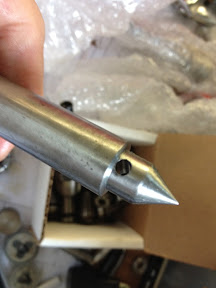
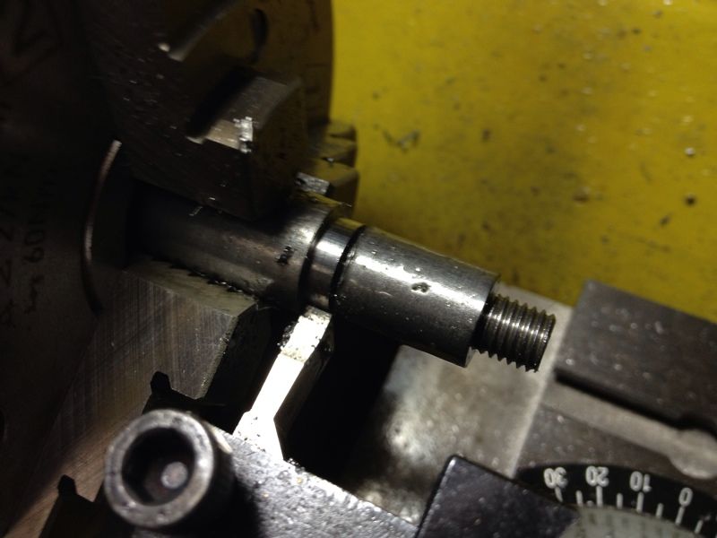
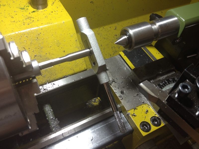
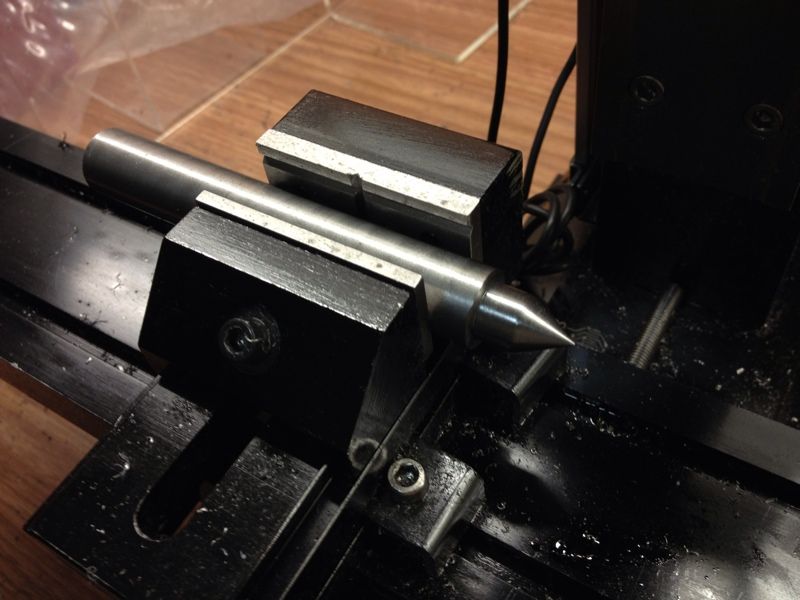
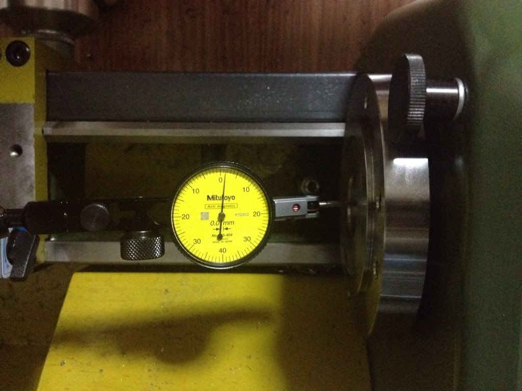
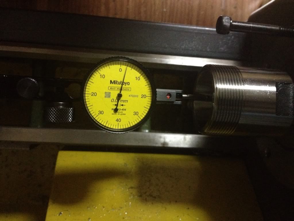
I finished the arbor with a thread hole to mount the partially completed 1/2 centre and fastened the threaded end of the 1/2 centre in it. This is what I have:


It wobble like no tomorrow. I therefore declared this to be good for the scrap bin.

I do not have another piece of silver steel in my stash bin and thought of using the piece of silver steel meant for the 2 adjustment screws that came with the kit. The 5/8" diameter silver steel rod supplied is slightly longer than 5". Each adjustment screws is only slightly longer than 1". Then it struck me that the extra length is meant to be use to make the arbor... Argghhh... I'll cut a short section of 1.5" to make the 1/2 centre.

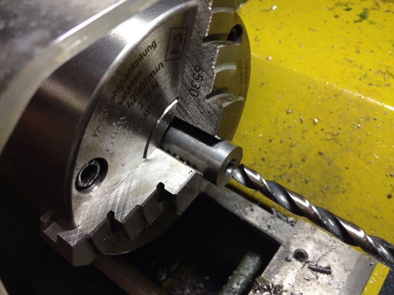
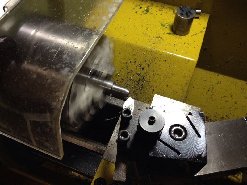
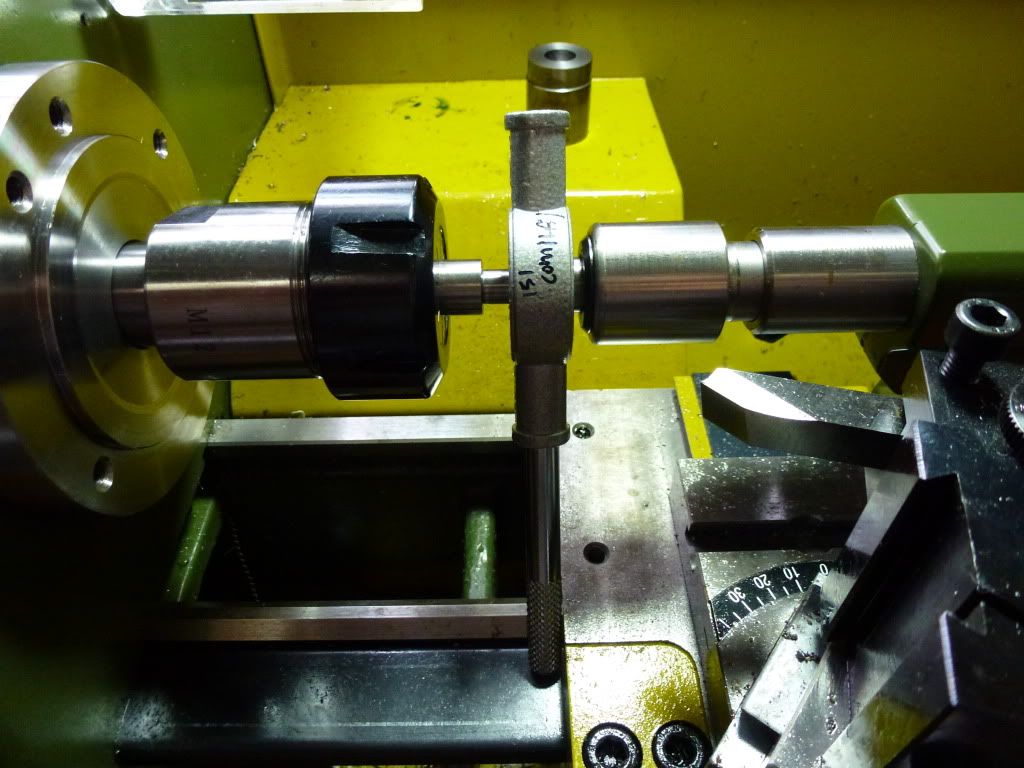
The much trusted 3 jaw chuck is now in use.
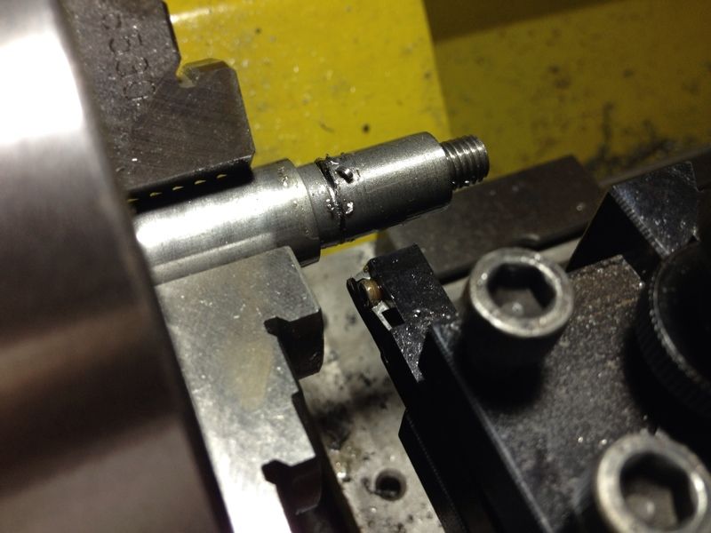
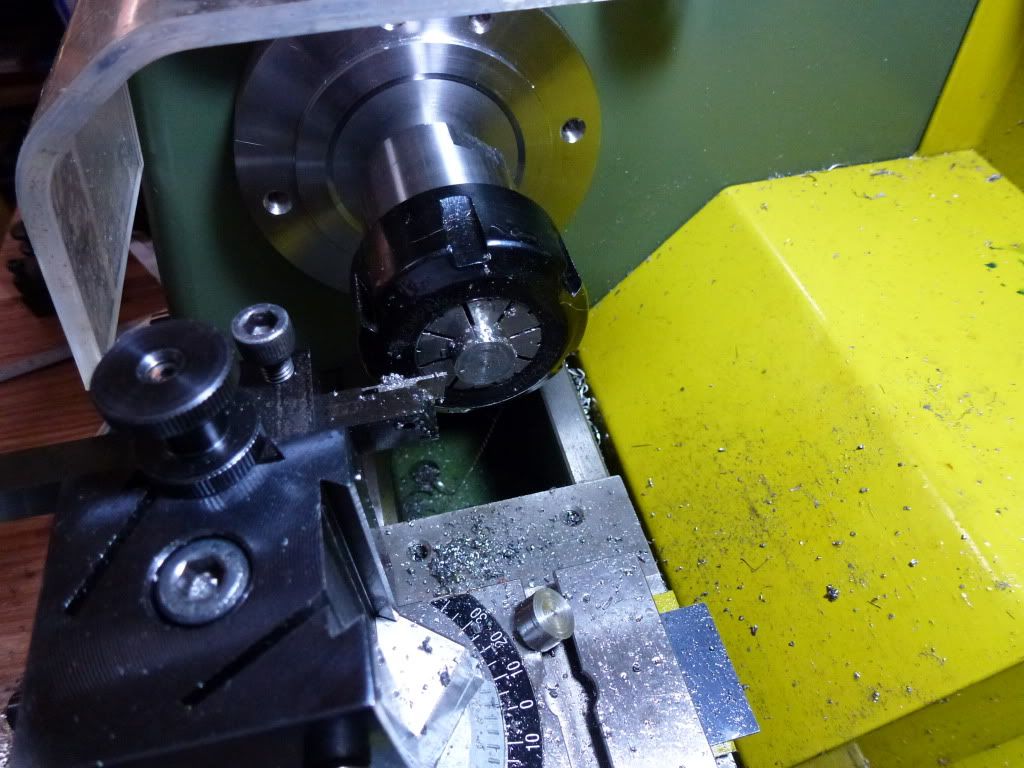
Facing the end square to prepare to turn slightly under 1.5" length to 0.5" diameter.
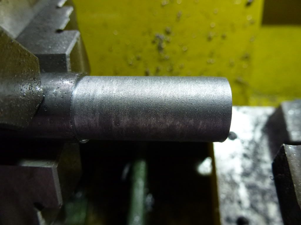
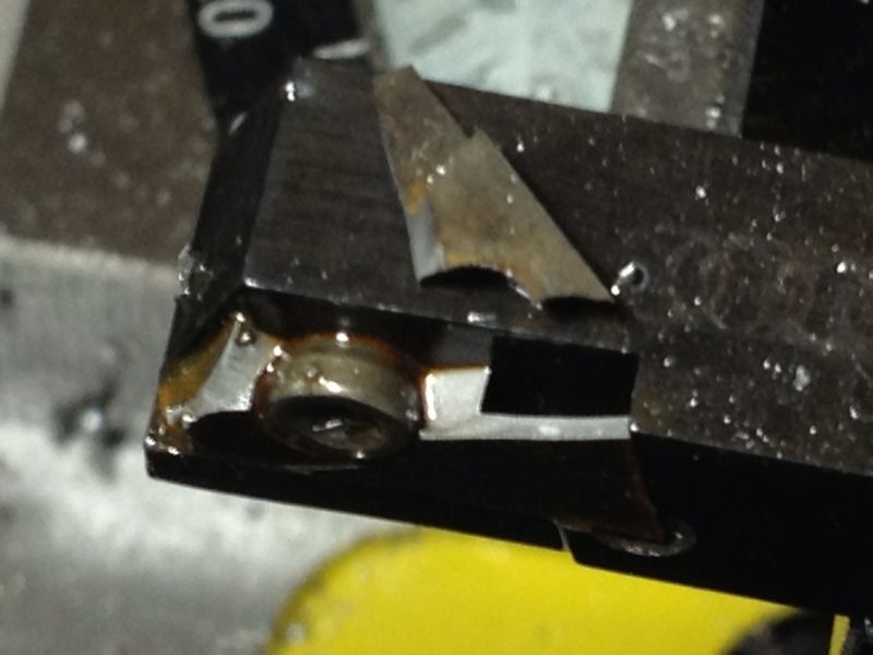
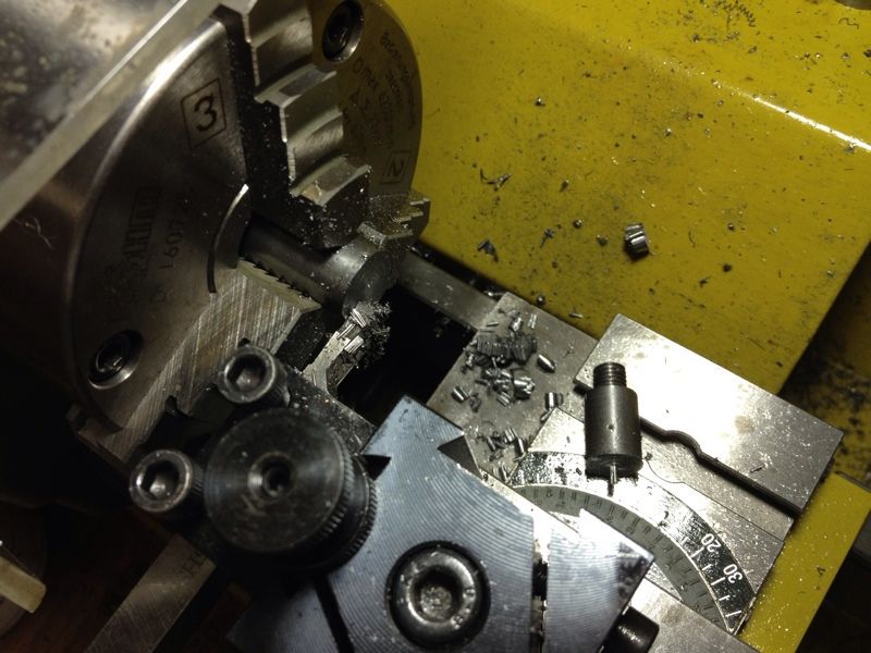
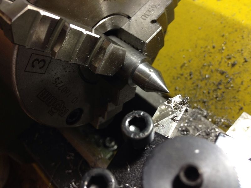
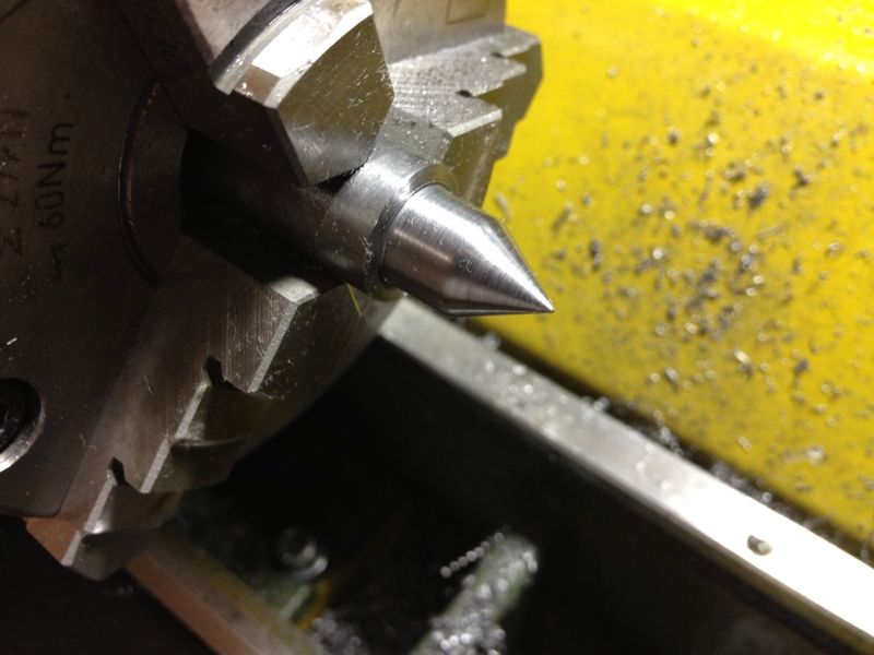
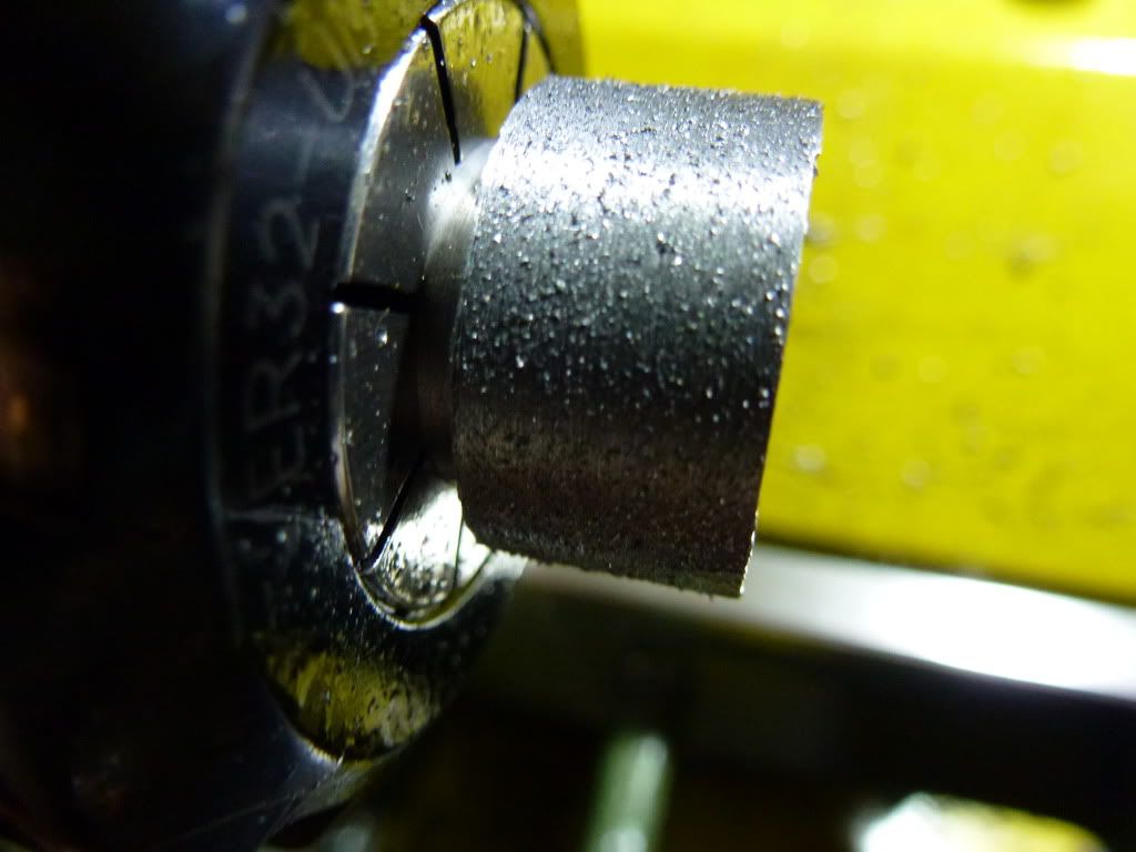
The finishes came as a surprise. It was so rough and looks the textual on a diamond file...
I stop work right away, not wanting to carry on till I figure this out.  The silver steel was turned with the HSS tool from Proxxon.  I tried turning with and without oil, spindle speed of 330 rpm and 660 rpm, advancing the tool 0.1mm to 0.4mm radius, feed slow, fast, and with autofeed.  The rough surface remains...

Anyone can provide me with a solution to this and the reason why this occur?  Appreciate any help.


- Posted using BlogPress from my iPhone

Saturday, March 17, 2012

Hemingway Set-Over Centre: Making the 1/2 Centre - Part 1

The 5/16" BSF threads was cut in the lathe this morning using 1" button die mounted in the die holder made originally for the Sherline tailstock but with the 0MT 3/4-16 adapter removed. The operation was completed without surprises and I'm happy with the result.
When I got home at night, I cleaned up the threads and parted off the 1/2 centre to length.  Next would be to make an abor with a 5/16" BSF tapped hole to hold the partially completed work to turn the 60-degree point, which I'll only be able to continue tomorrow before leaving to church.
The silver steel supplied by Hemingway in its kit.
Putting on latex glove to prevent chips pricking through the skin of my hand. Painful to remove the splinters without the glove.
The ER32 collets. The set was bought from CTC Tools many months ago.
Turning down to 7.94mm diameter to accept the threads.
Putting on the chamfer.
Getting ready to apply the die.
Using the die holder I made for Sherline lathe. The live centre was pressing against the threaded hole of the holder while I try to start the thread. Not very easy.
Switching in the die handle with one of the handles removed. The handle was bearing against the lathe bed while I turn the spindle with the wrench.
Testing the threads with the Base. It should be the Slide I'm supposed to fit this, but it doesn't matter. May need to turn an undercut to allow The 1/2 centre to thread all the way into the Slide.
Taken out of the collet for photoshoot.
The would-be 1/2 centre refused to go all the way in. Gap is about 1mm. I shortened the length of the threaded portion by a little and did a 0.8mm under cut.  Now it goes all the way through.
Parting off to length + some buffer to face off.
The next step is to make an arbor with a 5/16" BSF threaded hole.  The job is to be screwed into this hole to have the 60 degree taper cut turned on the opposite end.  I went through my bin of steel but couldn't find any suitable size rod for this.  What I've is mostly long 1" steel rod which needs to be cut on the bandsaw for use.  Its too late to do the work on the bandsaw for fear of angry neighbours pounding on my door and I'm too tired to saw it by hand.  I was about to call it a day (or would it be "night"?) when I saw this tap guide I did when I first bought my Sherline lathe.  I put it in the collet chuck and started turning it down a little but...

What happened?!
I ran a file on the surface to clean up the ugly looking finish and faced it flat.  I'll be drilling through to enlarge the hole for the 5/16" BSF tap.
I'm totally wasted... its only 11.10pm and I'm feeling so tired.  Time to stop before silly mistakes are made that can hurt myself.  Will continue tomorrow, if time allows.

Wabeco F1200 Mill

Looks like I'm doing it again, bearly 3 months after I received my Proxxon PD400 - I'll be going in with Mike to buy a unit of the Wabeco F1200 Mill each.

The model I'm getting is the most basic they have and their least expensive unit I'm willing to break my piggy bank for.  The other constraint is on the limited space I have in my home shop.

This is how it looks on www.wabeco-remscheid.de (the photo and drawings are from the Wabeco site):

I don't know what the 'E' stands for but this should be the unit I'm getting.

The machine, according to the specs given on the website, weighs 85kg, which is a concern to me as I don't know if my work bench can take it in operation.  I stood at my shop looking at the bench area and decided to have it on the spot where the Proxxon PD400 is sitting.  That's the area with sufficient support beneath the bench for drawers and stuff.

The dimensions from the front and side are given below:

It sure looks small from the first pic in this post till you look at the dimensions, especially after taking into consideration the space required on both side of the mill to transverse the X axis.

From the side.  Vertically, I need to allow about 1000mm (or 1 metre) for the Z axis to traverse.  Due to the window grill behind my bench, I'll have the handwheel portion of the mill sticking out of the benchtop, which is fine for easier turning of the wheel.

From the dimensions given above, I realized that I'm hitting the limits of the bench space.  This means that I'll have to release the bench space currently occupied by the Sherline 5410.  I'm quite reluctant to do that as I'm in the midst of installing the iGaging scales and DROs on it.  It is also very convenient for smaller jobs with the available tools and accessories in the shop.  Maybe I'll start by giving it some floor space beneath the bench as it is portable enough to be moved.  Unless someone can offer me an attractive enough price to take it off me, together with the Horizontal Milling Conversion Base and the iGaging scales & DROs.  But... how much is attractive to tempt me to sell? I've no answer.  Don't really like to selling my stuff though I've been a salesperson for all my working life so far...

I'll take that as a good problem, a blessing rather than lack.  I thank daddy God for the blessings showering at me despite what I am and what I am not.

Thursday, March 15, 2012

Run-Out

I was up early this moring as Alicia needs to be in school by 8am.  Got up at 5.30am to get myself ready and have to drag the big girl out of bed to prepare herself.

While waiting, I went into the shop wanting to find out what's the run-out of the lathe spindle and how much is added to that run-out when the ER32 collet chuck is mounted. Proxxon indicated the run-out of the spindle bore to be 0.005mm on their website without chuck mounted.  My setup to measure the run-out may be flawed but this is what I got:
I wish it was parallex error I'm registering but it is not.  I'm clocking 0.015mm run-out, 3 times more of what Proxxon advertised, on the 0.01mm mike.
Adding the ER32 collet chuck "enhanced" the number to almost 0.03mm.
My question is, is this too much? Should I be contended with what I've got? What kind of error would this translate too in parts produced?

Anyone?