Monday, May 28, 2012

Transfer Screw's Point

I don't know if there is a technical name for the point on the transfer screw that put a little depression on the stock. But I think you know what I am referring to.

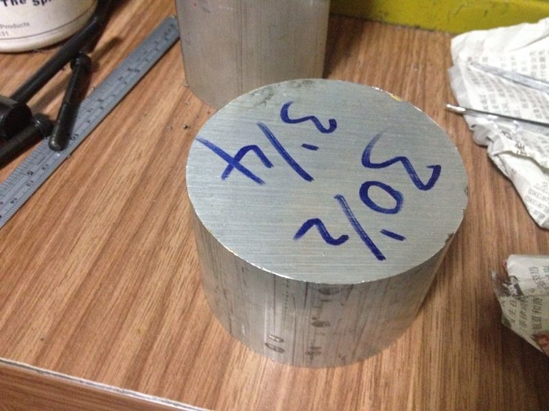
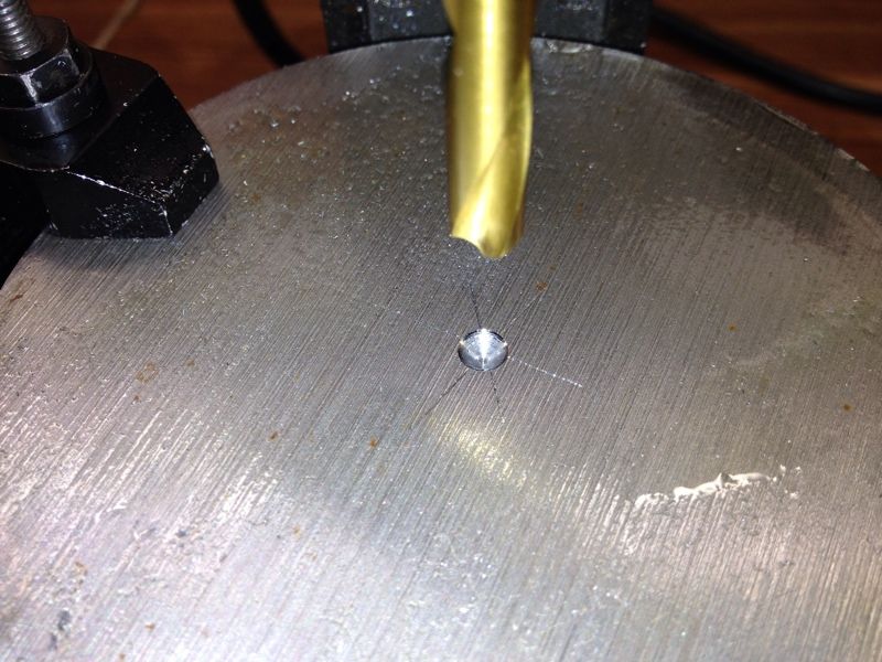
This post is not about making the transfer screws as the set I bought is now sitting at the Post Office waiting for my collection. It is about my attempt to make the point like what was shown on Bob Warfield's website (www.cnccookbook) as shown below:


I've been wondering how he did this. What I did before was to have the base of the point (which is basically a cone) equals to the diameter of the rod or screw.

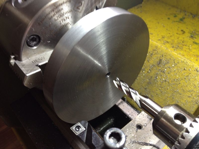
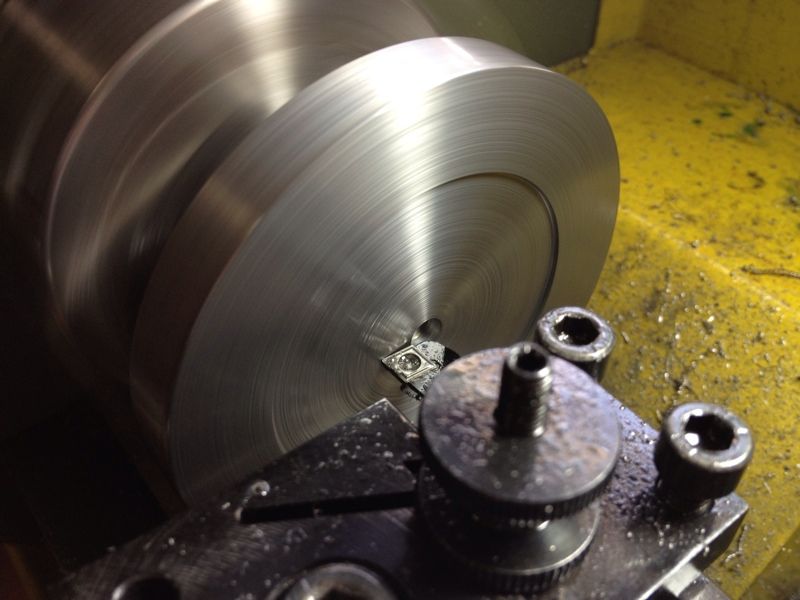
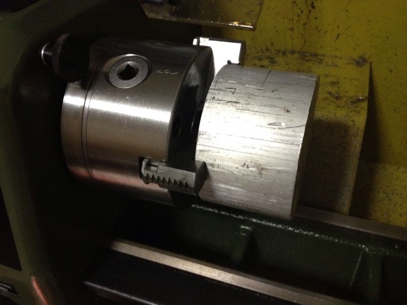
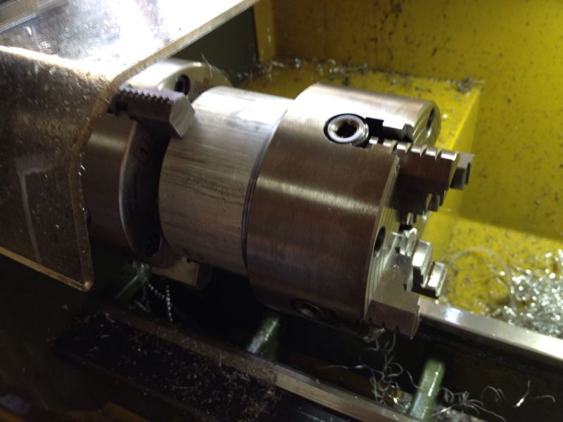
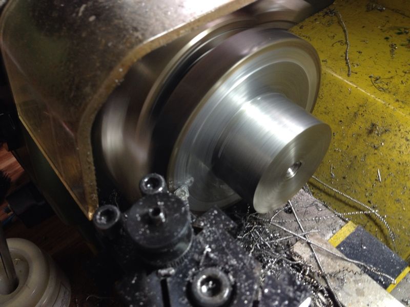
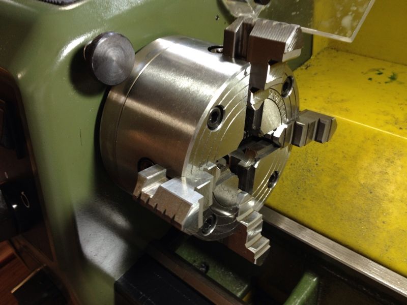
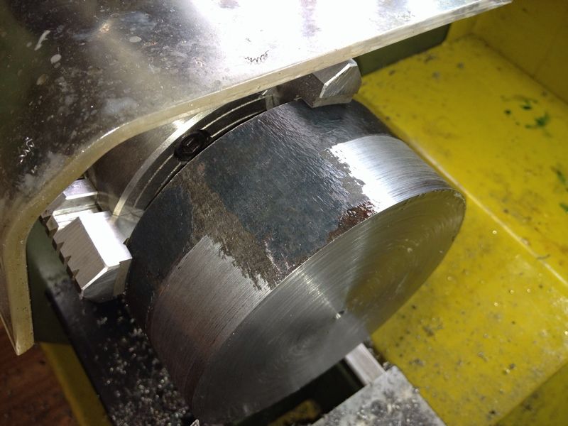
This morning, before leaving for work (I know it's Sunday and it sucks to be working on the Sabbath), I did an experiment. An M6 cap screw was mounted in the 3 jaw with its hand sawn off using a hacksaw. The top slide was turned to the 30-degree mark on the graduation and advanced to make the cut. I tried stopping at around the same Z depth and in no time, I get the result I want:


That made my day!!!

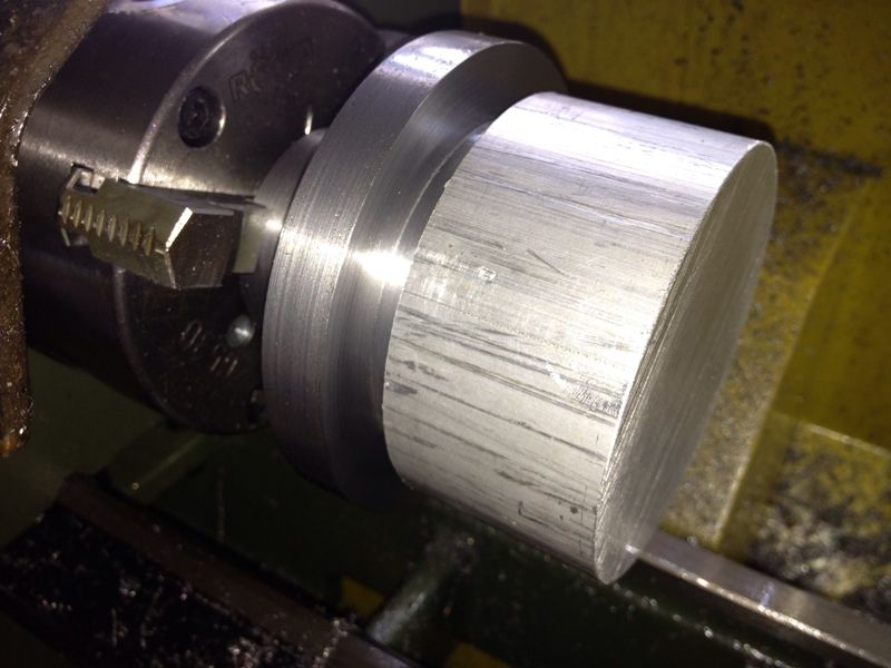
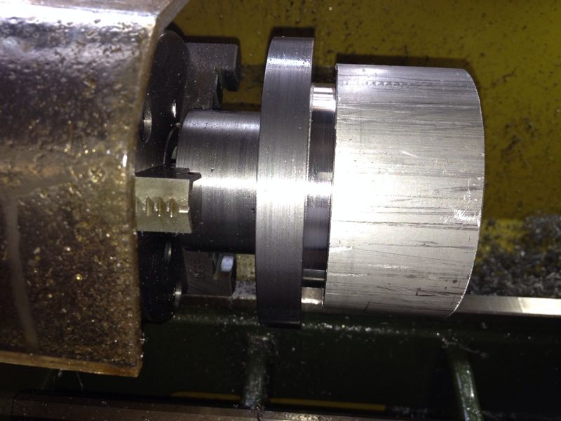
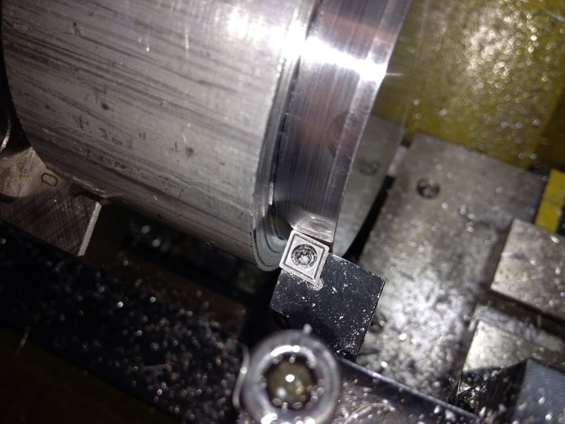
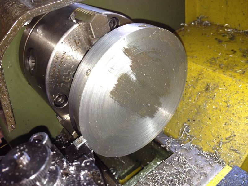
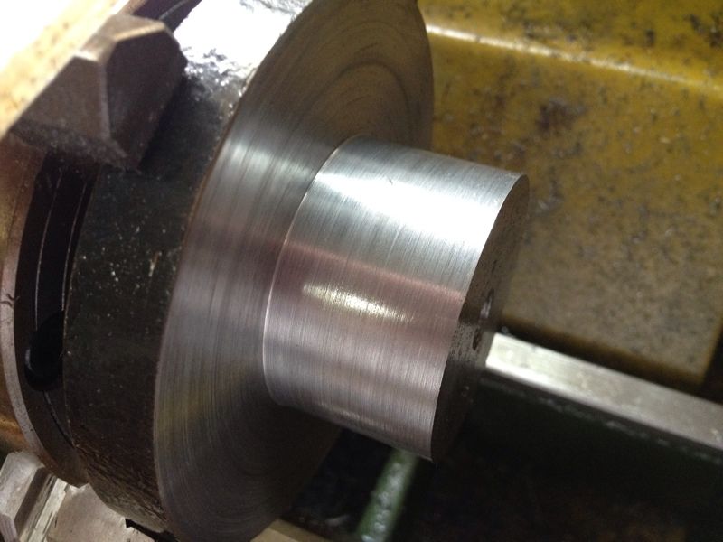
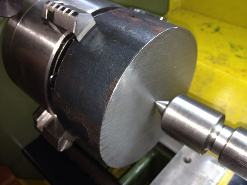
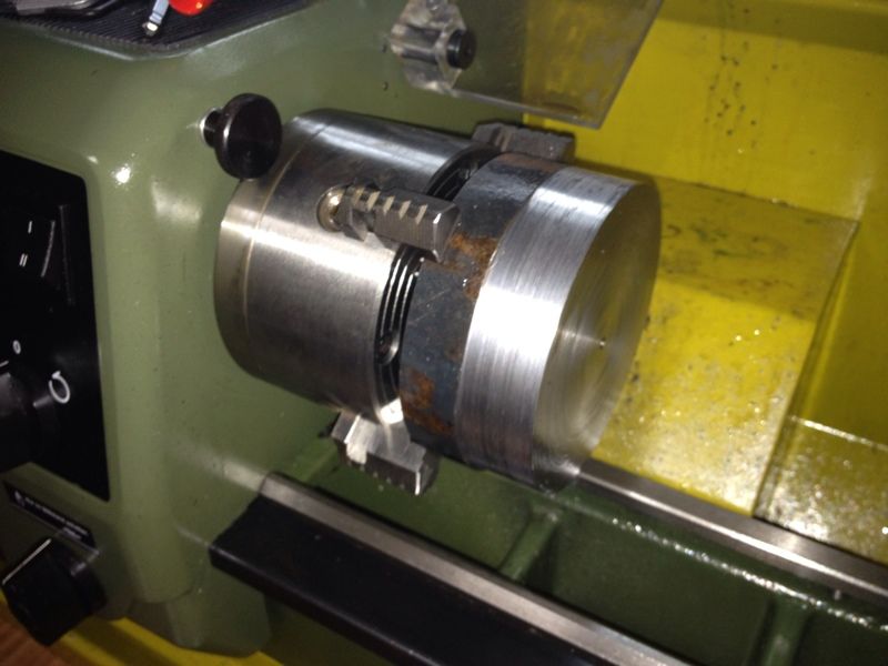
The point wasn't hardened. It works alright on aluminium but could stay sharp for a single use on steel. If you observe the pic above carefully, you'll see that the tip is a little blunt. This pic was taken after testing on both aluminium & steel.


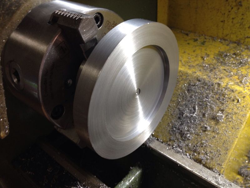
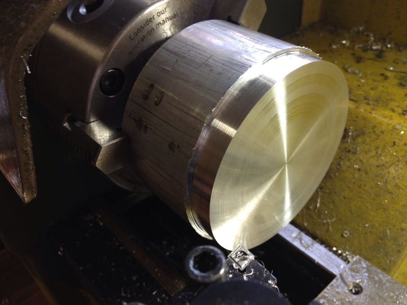
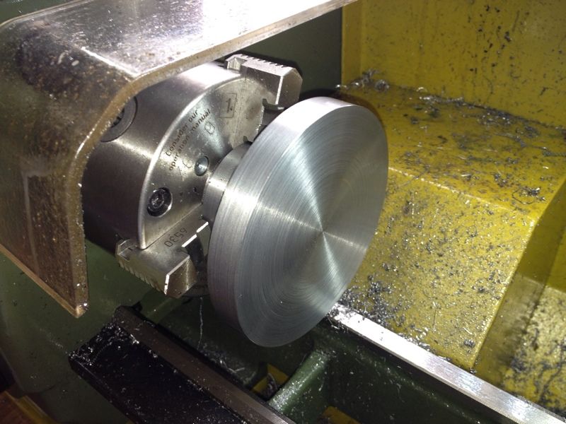
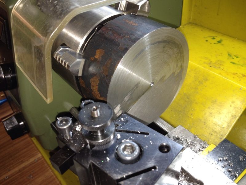
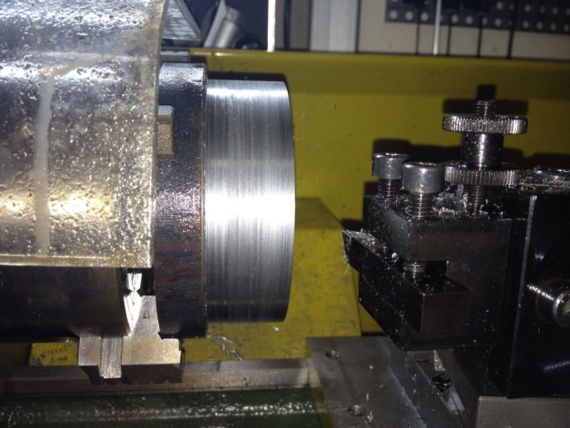
This was when the piece just came off the lathe.

But I still leave for work happily as I now know how it is done.

- Posted using BlogPress from my iPhone

Sunday, May 27, 2012

Broken Lathe Guard and Noisy Belts

I had a surprise the other morning when I saw the acrylic cover on the lathe broke from its swivel base. I don't remember breaking it during the last session as that will be pretty obvious looking at the way it is broken. 

Anyway, there is a magnet at the swivel base that cut off power to the lathe when the cover is lifted up. It does gets in the way when turning big diameter stock close to the spindle but it prevent accidental touching of the spinning spindle when in operation. 

I wonder if I should replace it or Loctite the magnet on the swivel base to allow the spindle to work without it. Those safety conscious folks may jump with it off but... I don't know. Will think about that.  Anyway, I ordered the replacement and it should be on its way from Germany.


Some noise from within the gear compartment was also heard when the spindle was spinning.  I opened the cover to have a look and saw these:


No, the belt didn't come off the pulley.  I took it off for photo shoot and to cut away the frayed portion.
I'm wondering, given my only 2 to max 4 hours of usage every week, if its too soon to result in these?  I'll still proceed to order the 2 belts in cases of more damage.

Saturday, May 26, 2012

Blogging on the new site

I'm trying to make a decision here; to write my blog posts solely on my new site or still update both Blogger and the new site.

The decision would be simpler if I'm able to write once and post on both, pics and words, all at one time.  But so far I've not been successful.  Posting both sites requires quite some bit of work, especially with pics.

What's your preference?

The new site can be found here: www.wongstersproduction.com.

Take a look and tell me what I should do.

Regards,
Wongster

Sunday, May 20, 2012

ER32 Collet Chuck - Test Fit

I was rather curious to find out if the recess fits the bore on the spindle flange. Went back to the shop and take everything off and fit the work.


It seems to fit nicely...


Pushing the flange of the chuck to be against the flange with one hand, I tried moving the chuck against the registration boss on the flange. I can feel slight movement and some knocking sound at certain point... boy am I disappointed...


I put on the 3 jaw chuck (without the bolts) and did the same. The slight movements and a little knocking sound was also there.


I measured the gauge with the caliper - 70.01mm.  The registration boss on the spindle flange measures 69.99mm.  That means that the recess is 0.02mm over sized...  No wonder the gauge fits so tightly into the recess of the 4 jaw chuck.  I've to press it in with my hands.  If the gauge is oversize, the recess will also be...


I'll push on till the end to complete this project.  The decision of making another piece will be left till the completed collet chuck is tested.

ER32 Collet Chuck - Recess for the Register Completed

I was up as early as 7am this morning.  Wanted to sleep in on this Sunday morning but just could not.  After washing up and 2 cups of coffee, I started working in the shop.

The job of the day is the recess at the back of the chuck which needs to be precisely done so that it fit the registration boss on the spindle flange without any wobble.  I asked Dave my last couple of questions on the forum so that I've clear images in my mind of how I should carry out this operation.

Not much pics taken as the session was rather short.  I was concentrating intensely when bring the recess to its final size.


After starting a shallow hole with the centre drill and 5mm drill, a slightly larger endmill was used to open up the hole a little more.
The Sherline insert boring tool was used to open up the recess to slightly more than 60mm.  This is to leave some "meat" on the wall of the recess after I get close to the depth.
The gauge made earlier was used to test the recess bore.  It fit nicely but the air within the 2 mating parts refused to let the gauge sit properly.  I tapped it in with the palm of my hand and couldn't get it out after.  It has to be pried out carefully with an allen key.
From another angle.  The shiny part is the gauge.
All done for the recess.  I let it cool before testing it again with the gauge.  I believe the air pocket formed is an indication that the fit is a good one.  I definitely hope so.
The "floor" of the recess was finished off as best as I can.  It feels smooth now but doesn't have the bling shown in Rob's and Dave's pics in the forum.  It makes me wonder if its the camera as mentioned by some other members of the forum. Mmmm... 

Next up, the mounting holes.  The 3 holes are clearance holes for M6 cap screws.  After completing the recess, I suddenly realized that I have forgotten to scribe the PCD for the mounting holes... All is not lost, me think.  I've on order from Little Machine Shop in US a set of M6 Transfer Screws.  The recess will help to locate the collet chuck while I tapped the part to transfer the hole locations.

This is how the set of Transfer Screws looks like, for those whom I tried asking if they're available in SG.


Pic taken from Little Machine Shop.


The threaded portion is to be screwed onto the mounting hole on the spindle flange, leaving the little pointy portion sticking out.  The collet chuck will then be placed onto the flange using the recess as a guide.  It will then be tapped with a mallet to have the hole positions transferred to its back.

But I'm still concern about one thing; will the trapped air causes the collet chuck not seating properly affecting the transferring of hole locations to be off?

I'll know when I received the item, together with a 3" angle plate.

That is all for today.  Have a blessed week ahead with unceasing fruitfulness!  Shalom.

Saturday, May 19, 2012

ER32 Collet Chuck - Turning The Recess

This post is also available on my site here.


I finally found a suitable piece of aluminium  to make the gauge for the recess.  It was cut off from a long piece of 81mm diameter rod.  No much of convincing required this round to get the piece I want.  I've also collected the 80 degree insert tools from Mike.  From my reading online, it is good for roughing due to its shape.  The pair of left and right tool cost me SGD124 if I remember correctly.

With the right stock on hand, I happily turned down the aluminium block to close to the required dimension and slowing turning bit by bit till it fits the recess at the back of the 4 jaw chuck.  After playing with steel for a while, I find cutting aluminium fast and easy.  The job was quickly completed.

The half done ER32 collet chuck was remounted on the 3 jaw chuck to clean off the remaining skin and the back faced.  I'm now ready to turn the recess. 


The 81mm diameter aluminium piece of 50mm length cost me SGD15.
Onto the 3 jaw chuck it went.
The new 80 degree insert tool in use.
A section of about 10mm turned down as the gauge. The 4 jaw chuck was used as a gauge to for making this. A little was turn off each time till I am able to fit the 4 jaw chuck on.
No apparent movement felt when the 4 jaw chuck was mounted. The fit was slightly on the tight side.
Posing for photo-shoot. If you look closely at the side of the gauge, you'll see a line which was created by the recess of the 4 jaw chuck.
Turning off the remaining "skin". No so fun as the hot chips kept hurting my hands and arm... ouch!!!
The back face was squared up next.
Job done. My cross slide wasn't smooth to turn. Its a bit on the tight. This is my excuse for the not so ideal surface of the back face... hehehe...


The experience gained while turning the nose helps.  I'm starting to get some feel of spindle speed, depth of cut, and rate of feeding.  Good that I'm feeling more confident in use the lathe.

The next challenge would be the recess, cutting the threads, and boring the taper.  I'll be taking it slow to gain more understanding of the process.

Sunday, May 13, 2012

ER32 Collet Chuck - Nose Job Part 2

This post is also available on my site.

Another short session today of about an hour to an hour and a half. The nose is now down to slightly below 50mm in diameter after "smoothening" out the surface. The spindle was bumped up to 660 rpm with very light cut using the Sherline's carbide insert tool. The tip on this tool has radius of 0.4mm. The result was great! The flange was also squared up and finished with the same method. I realised that I've to lock down the carriage to produce a decent finish when face turning. Also, I discovered that having a small relief angle between the edge of the insert and the work helps in the finish.
Facing the flange to square it up.
The surfaces feel smooth to the touch despite how they look.
From another angle. Should have smoothen out he face of the nose just for the fun of it.
Wanted to drill  through the centre of the work but changed my mind.  I mounted it in the 3 jaw chuck by the nose to see if I've enough clearance from the jaws to drill through.  This is not needed anymore as I'll only work on the bore after finishing the recess and mounting holes.
The biggest piece of aluminum rod tested on the recess of the 3 jaw chuck.  It is a tad too small to be made into a gauge for the recess I'm cutting on the workpiece.  A trip to Kelantan Lane is now unavoidable.

When I visit the metal shop at Kelantan Lane, I'll also be buying a thicker piece of Mild Steel stock as the material left for the flange will be a little on the thin side, unless someone tells me otherwise.

I've been thinking about how I should go about marking out the PCD of the mounting screws.  Of the 2 approaches I read, the one shown on an article posted on 7x12minilathe group seems easier.   The other one on Tools and Mods seems to me to be more accurate as it will be concentric to the lathe centre.  Any comment?

Another question, should I be boring and making the taper hole before threading or should I do it the other way round?

Like always, have a blessed week ahead!

Tuesday, May 1, 2012

ER32 Collet Chuck - Nose Job Part 1

This post is also available on my site.

The work on the Collet Chuck for ER32 started last weekend.  Up to today, I don't have much to write about.  This is the time I'm dealing with a large piece of steel stock and frankly, I've no confident that I can pull through this project to the required accuracy.

The mild steel stock I bought measures slightly bigger than 100mm in diameter and 42mm in length (or should I call it thickness?).  The edges around the circumference was deburred with a file before I started work.

The approximate centre was punched with the aid of a Centre Square and a rule. 
It was then fastened to the mill table with the step clamps. The drill shown in the pic has nothing to do with this ops. It was there from the previous job.
Trying out the new Spot Drill, which is a mistake. Should have use the Centre Drill as I'll be using the Live Centre on the Tailstock to centre the stock as best as I can in the 4 jaw chuck.
The 90-degree spot drill in use instead of the 120-degree shown in the previous pic.
Opening up the jaws of the 4 jaw independent chuck to slightly more then the circumference of the chuck body (100mm diameter).
It will save me the trouble of trying to locate the centre of the hole if the Centre Drill was used.  The jaws were carefully tightened around the job.
Facing cut was done first to square the face to the spindle rotation.
Then the side.  This piece has tough skin! I should have started with heavier cuts to go beneath the skin but I was scared of the job flying at me...
Finally, I've about 25mm section turned concentric.  This will be the section I'm bringing down to 50mm.
This was where I stopped - 90mm diameter and 40mm more to go...

I took a video of the turning in progress.  The chart I've on my lathe says that the spindle speed for steel stock of 100mm diameter is 80 rpm. I tried both 80 rpm and 160 rpm at depth of 0.1mm to 0.5mm per pass with the carbide insert tool.  I was trying to see how deep I can cut.  Don't really feel comfortable at 0.5mm  from the sound produced - it sounded like the motor was going to stall anytime though that didn't happen.  To play safe, I backed off from the depth to 0.4mm.  Now I wonder how long will I take to bring the 25mm section down to 50mm diameter at the rate I'm going...