My children will be going away with their grandparents to Malaysia tomorrow. Their mother will be having appointments from the morning till just before Mandarin Service at 5pm. Most importantly, I don't think its a good idea for me to be home alone with just the our helper. Not that I don't trust myself but I don't want any possibility of any false accusation should she be unhappy about things or is missing home. Anyway, there goes my plan to have a good 1/2 day in the shop making the ball bearing thrust collar for the X axis. I'll be going with her for her appointments (as her chauffeur of course...), bring the car to the mechanic to check the strange sound while accelerating from stop, and to pick her mom up for church. If time permits, I would like to drop by the metal shop to pick up some brass plate and free machining steel for some projects I've in mind.
Though feeling a little tired, I spent some time in the shop trying out a way I saw on MadModder on holding a thin piece of round stock in the lathe to machine the round surface. I've never tried that before though I saw some pics on some blogs/website of it being done. The thread Ross started on his oscillating steam engine build can be seen here:
http://madmodder.net/index.php?topic=6711.0. He was making the flywheel and holding it in the chuck jaws will not allow the cylindrical surface to be turned. A big washer with insulation tape covered evenly was used between one face of the flywheel and the closed chuck jaws and the other face held by the revolving centre on its centre drilled hole. Driving by friction, he was able to turned the surface down to the required OD.
I was wondering how I can turn the OD of the 15mm thick aluminium round stock down to 39mm diameter with the jaw gripping the OD. For the Y axis, the stock was 40mm long, providing a portion of the stock to be held in the chuck jaws. Now that I'm left with 15mm after the completion of the Y axis thrust collar, I'm unable to do the same. Ross' way of doing it may just work for me.
 |
| Changing the carbide insert to HSS. I bought this some time ago from AR Warner through LMS. |
.jpg) |
| Facing off to clean up the part. |
.jpg) |
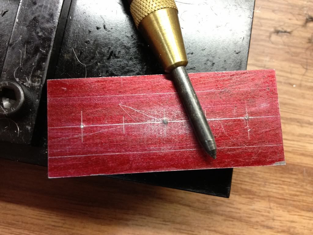
| Centre drilling the face to put a 60 degree hole for the revolving centre to bear against. |
.jpg) |
| Sticking insulation tape on the chuck jaws. This may be where this setup fail... I didn't use a washer to provide sufficient surface area. |
.jpg) |
| The revolving centre bearing down on the stock in the centre drilled hole. Some pressure was applied before locking the tailstock spindle in place. |
.jpg) |
| Light cuts were taken at around 0.05mm per pass. Nice... |
.jpg) |
| The stock start to shift out of position as I was just about 0.6mm away from the diameter I want. |
I took the piece out trying to think of a solution. Then I remembered seeing someone on the web using a bolt through the centre hole drilled in the stock. I rampage through my drawer of hardware to find a bolt of right size for the job. Found a small bag of bolts of 3/8" with washers and nuts. I quickly encountered the next problem - how do I drill the hole in the middle of the stock when I know that I will definitely hit the chuck jaws as the drill exits from the back of the stock? at 39.6mm diameter, the jaws were in its reverse direction. The step on each jaw gives very little room for me to clamp down the stock and no room for me to insert a piece of parallel to do that. So, over to the mill I go.
.jpg) |
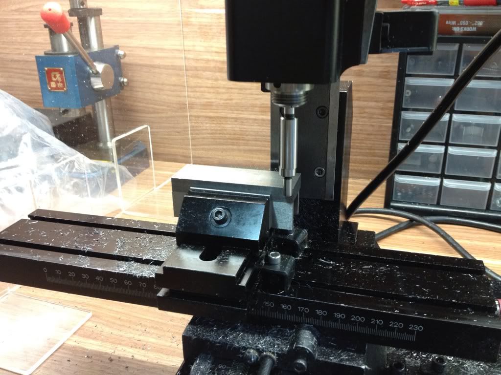
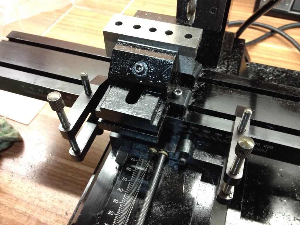
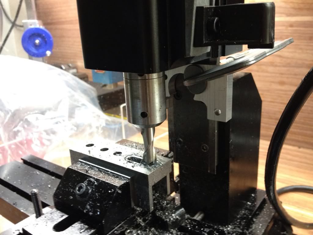
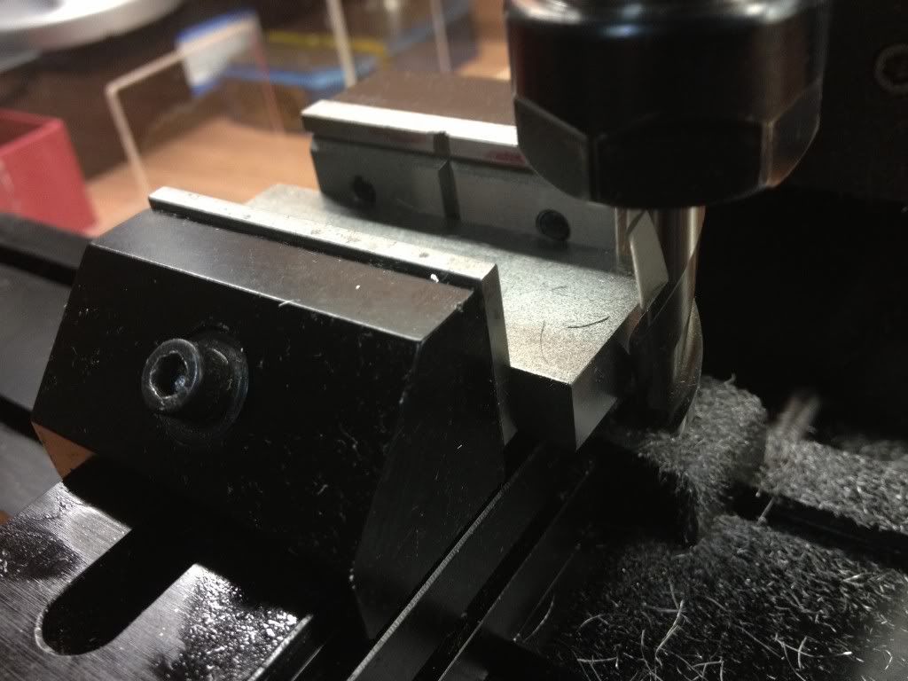
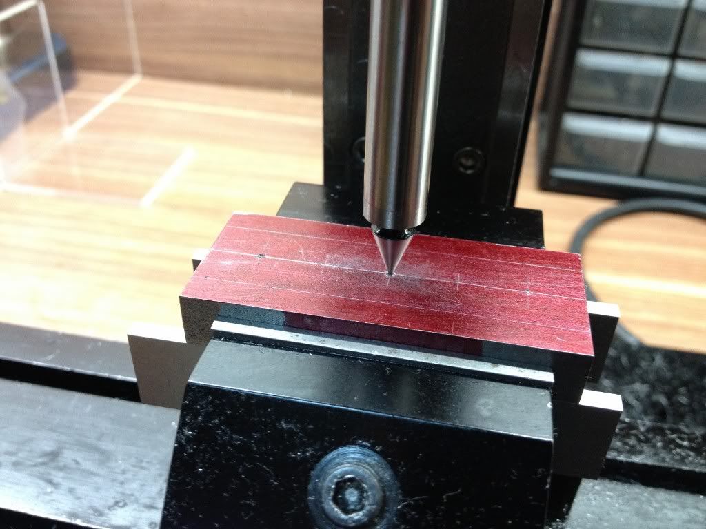
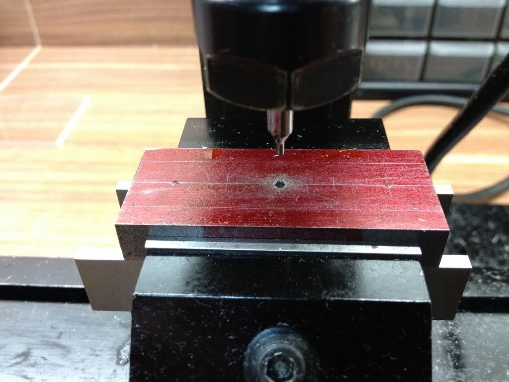
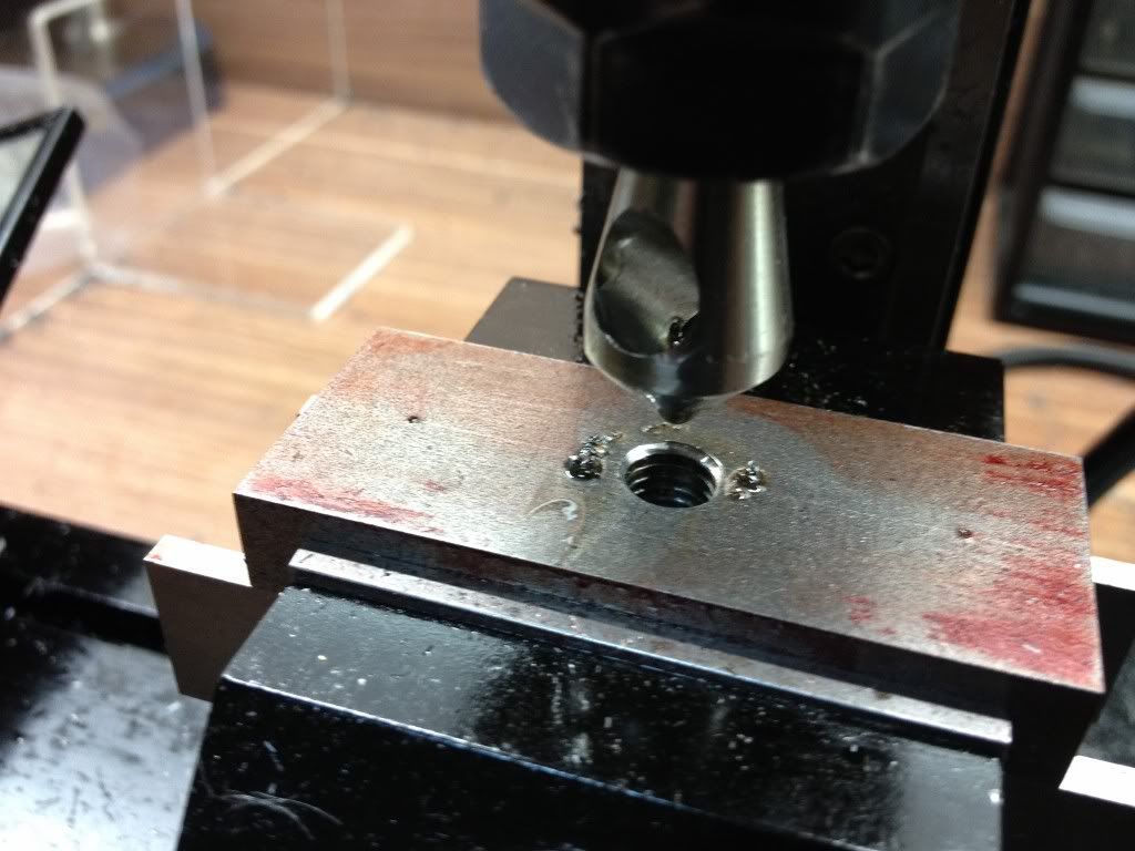
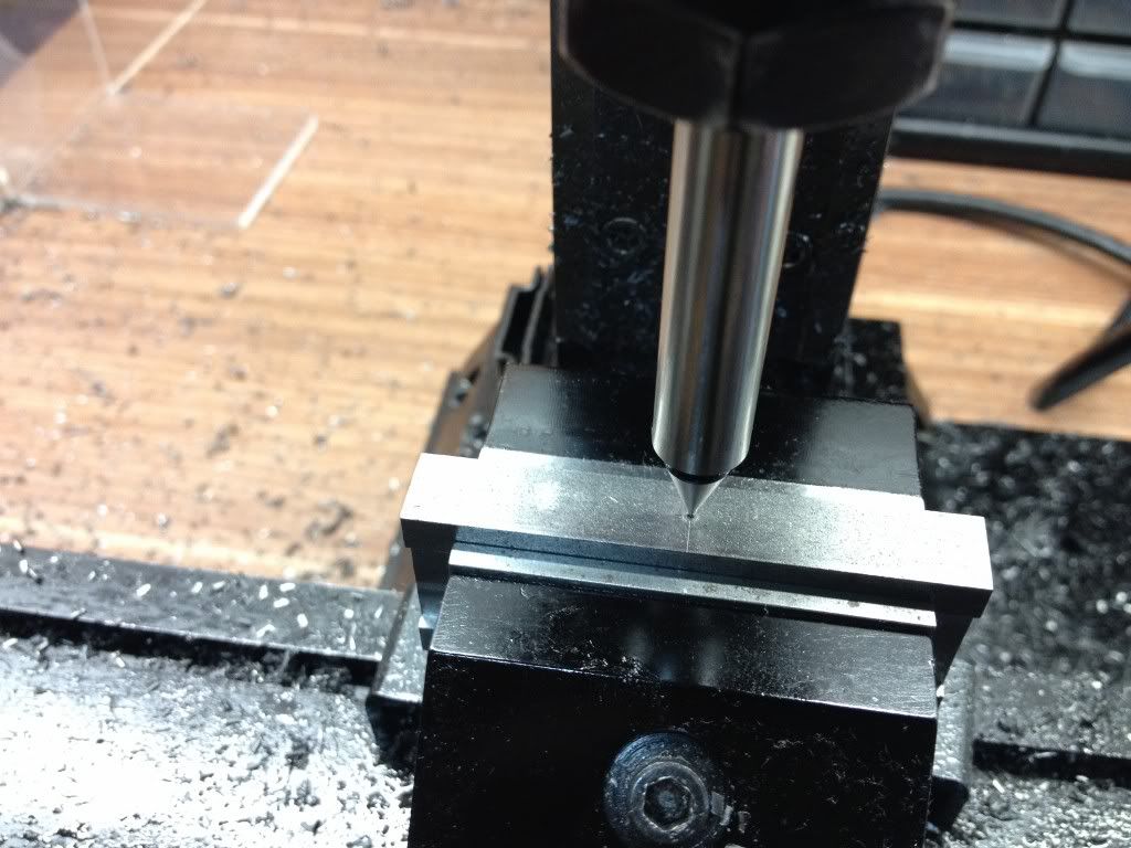
| The spindle was centered using the centre drill hole with the MT1 dead centre. This don't have to be very accurate as I still need to drill and bore the centre hole for the bearings. |
.jpg) |
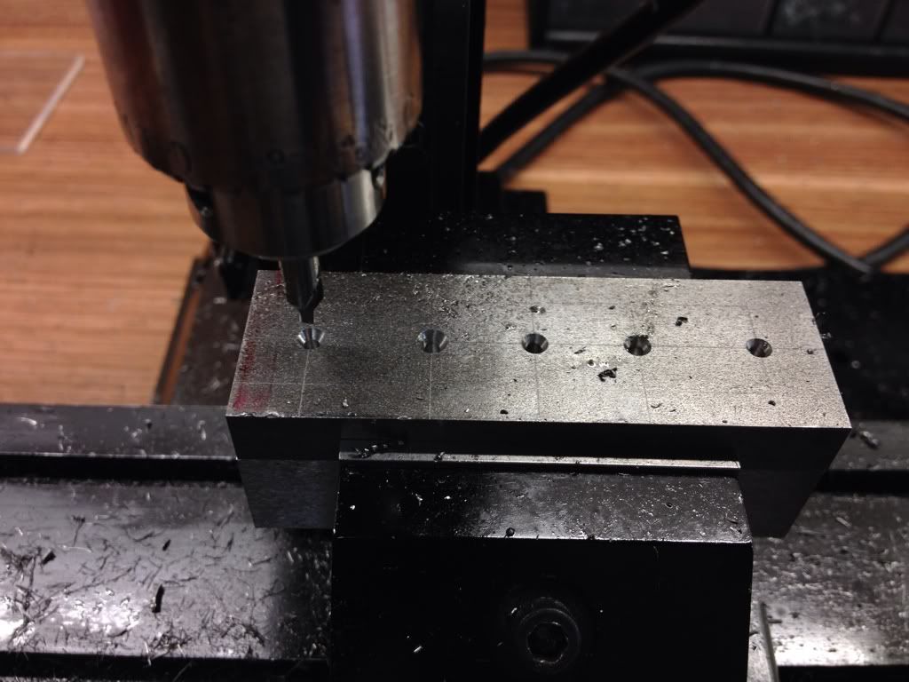
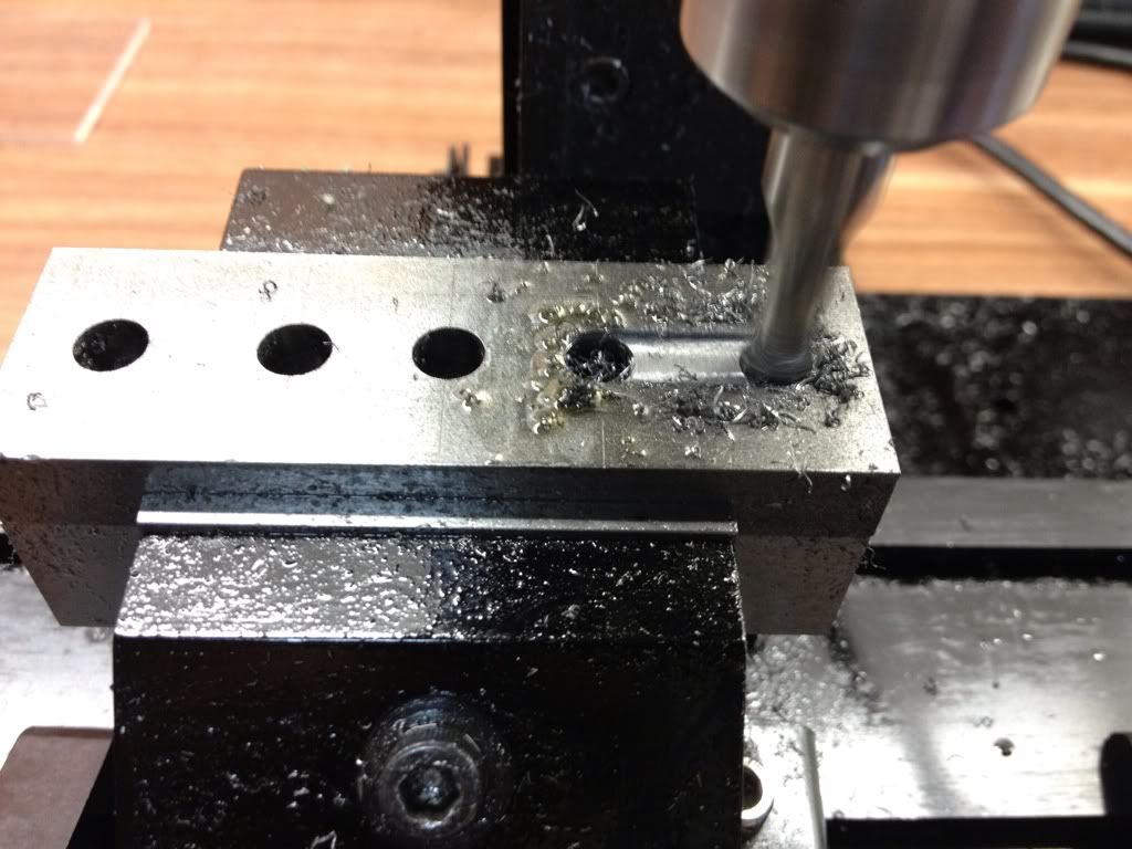
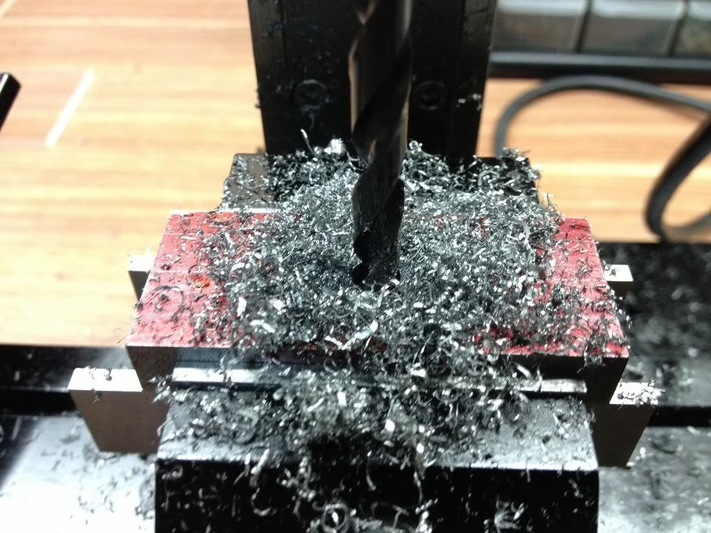
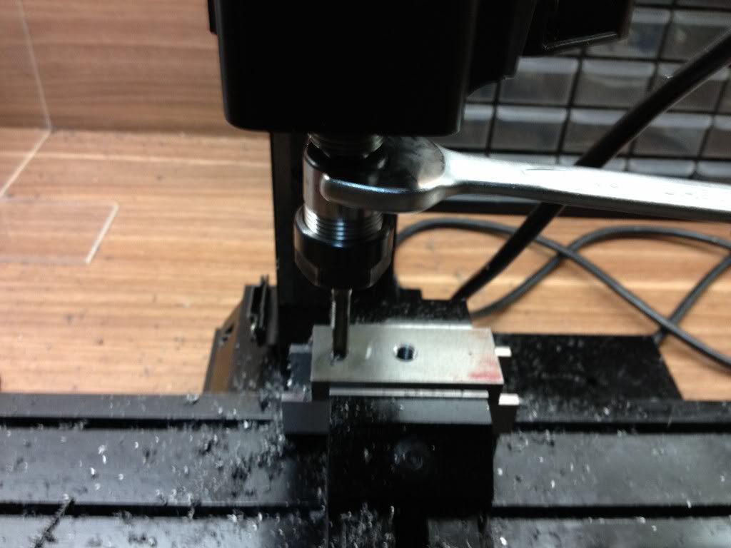
| After drilling through with a 6.5mm drill, I took out the 3/8" drill to enlarge the hole for the bolt. But the drill is too long to be used on the 5410... |
.jpg) |
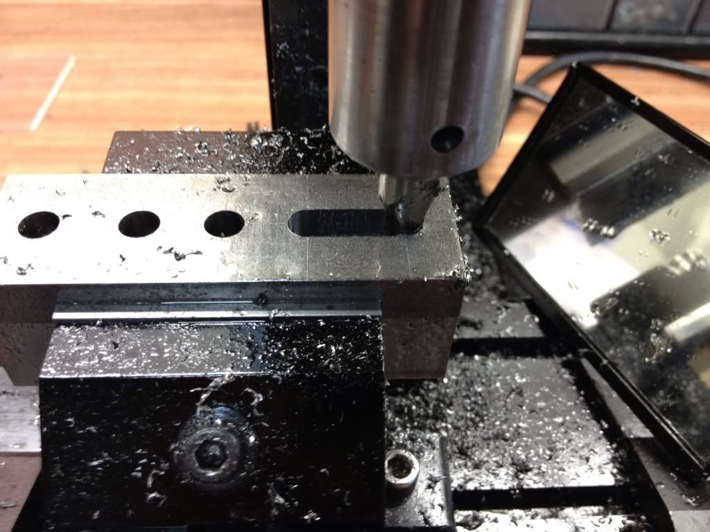
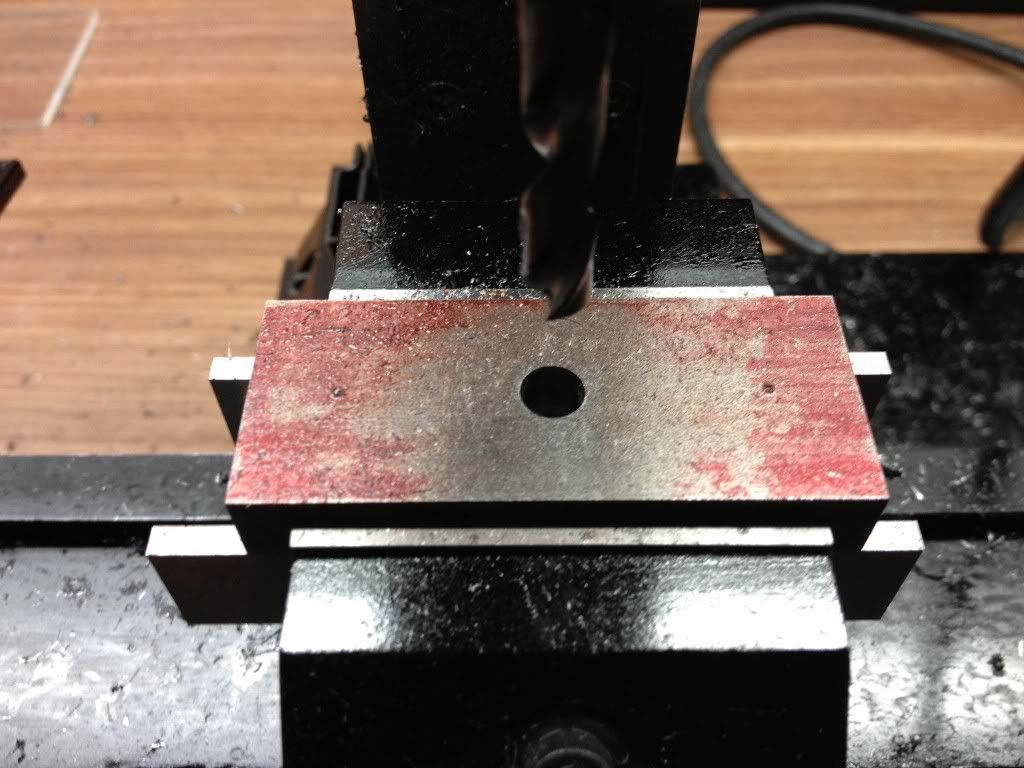
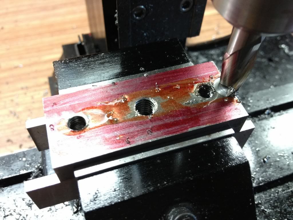
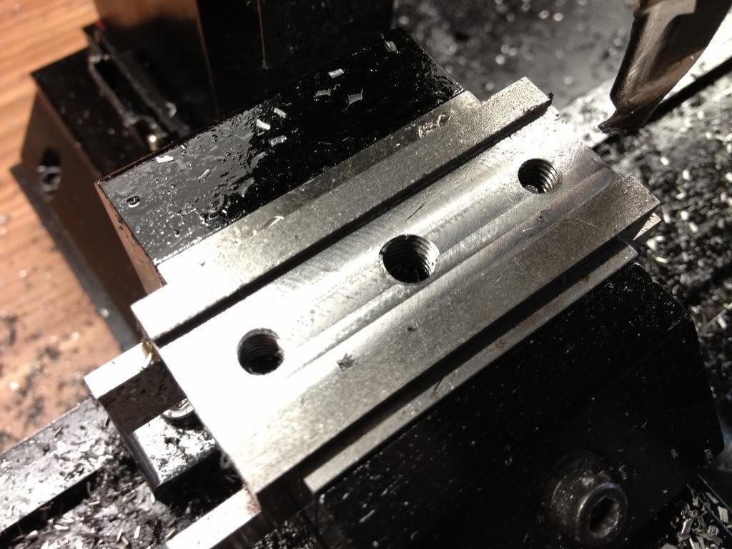
| Found another bag of bolts and nuts that are smaller than 3/8" (can't remember the size. Sorry...). The drill for this bearly clear the stock. Anyway, managed to drill out the hole I need. |
.jpg) |
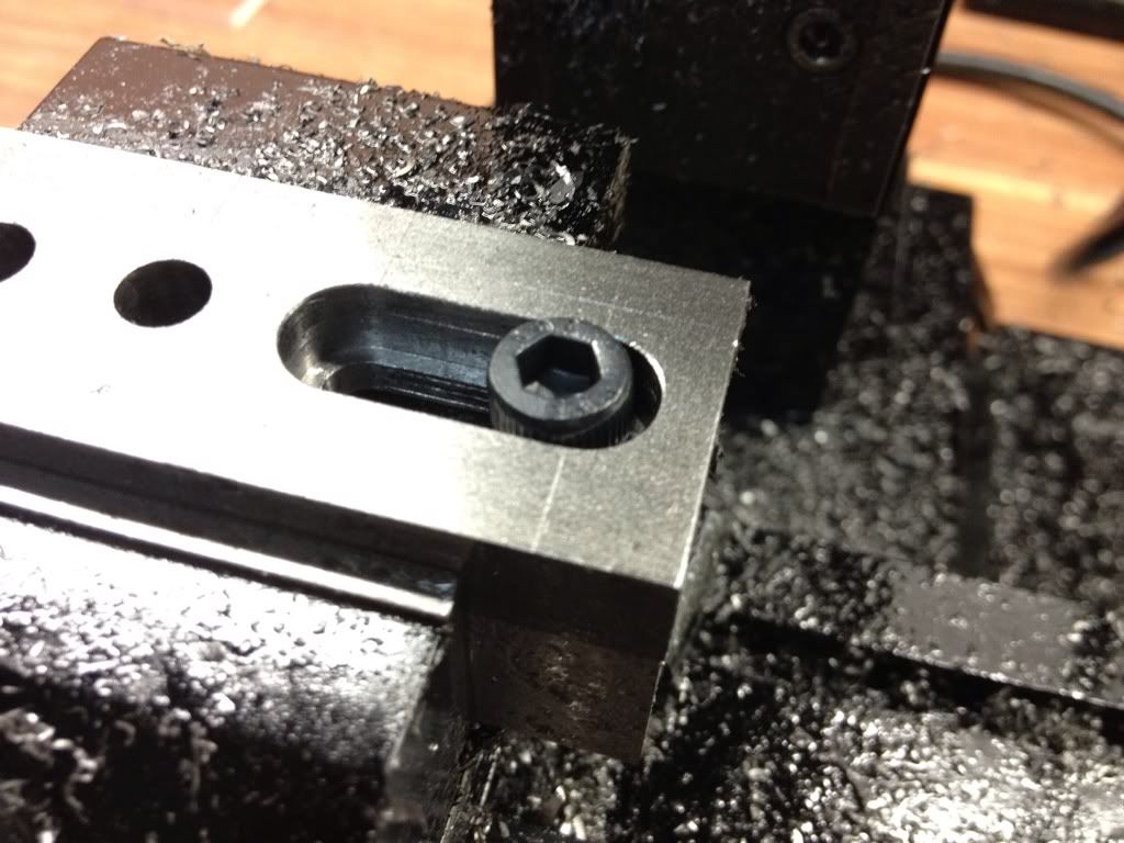
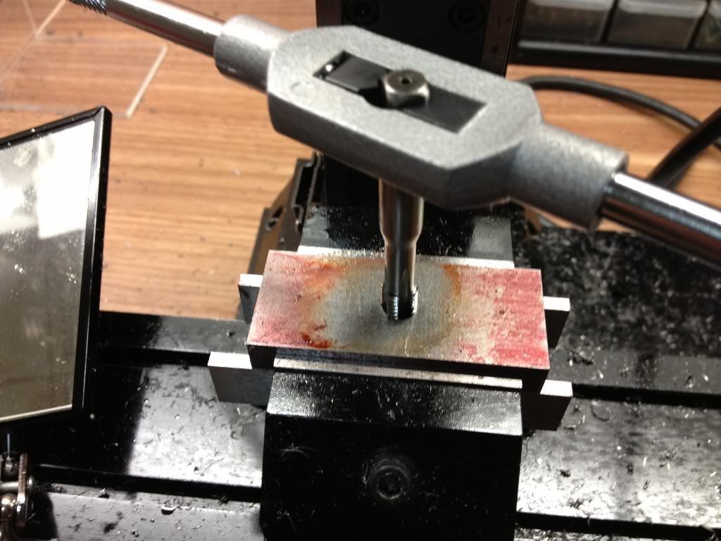
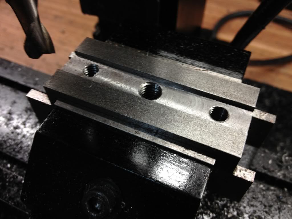
| Test fit with the bolt. Just a slight wiggling room can be felt. This should work. |
.jpg) |
| Fastening down the stock in the bolt. |
.jpg) |
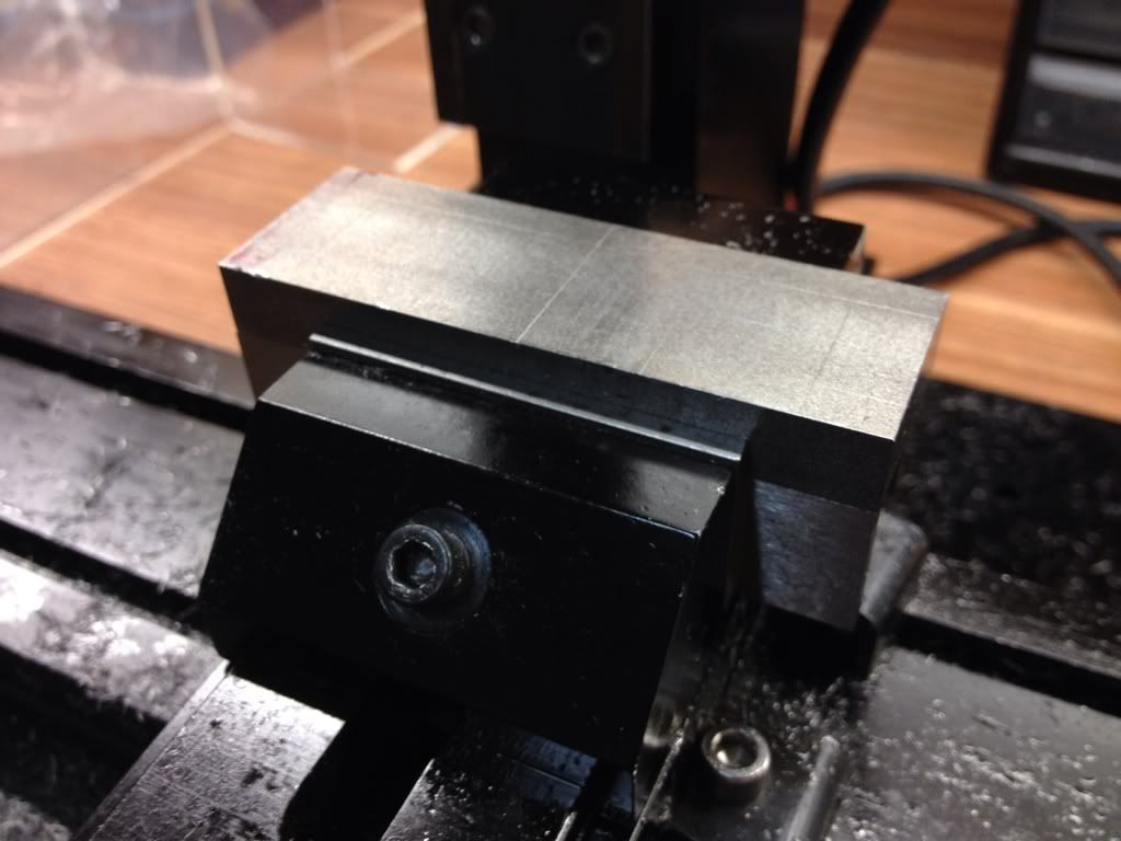
| And into the lathe it went... |
.jpg) |
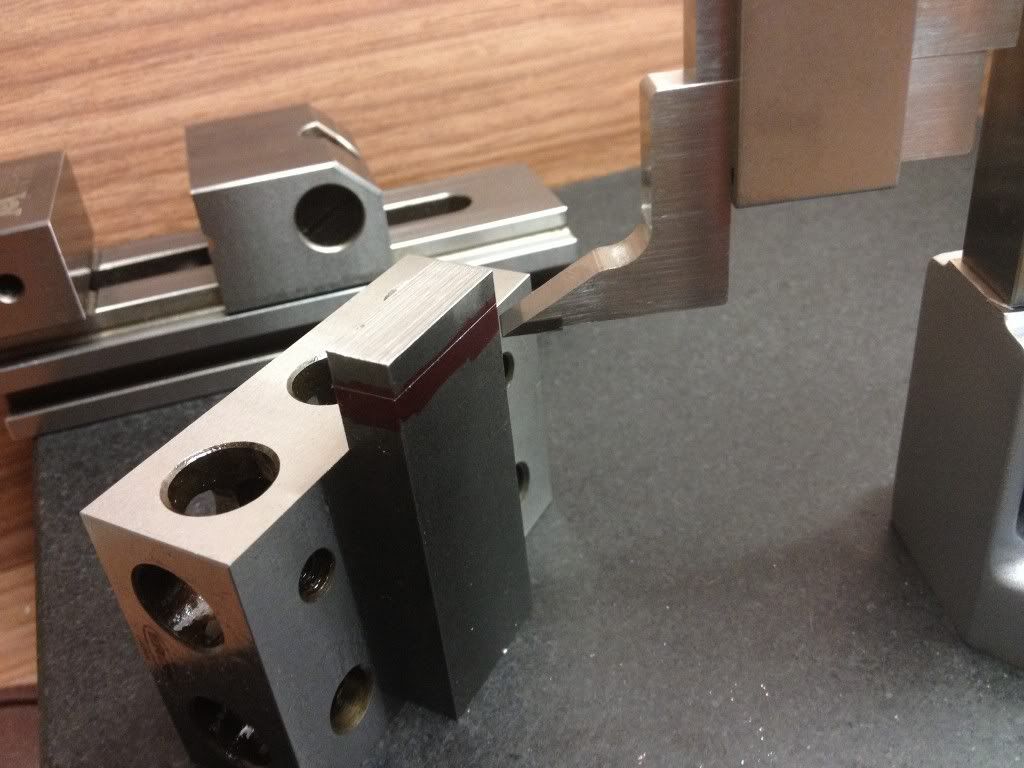
| From the side. |
.jpg) |
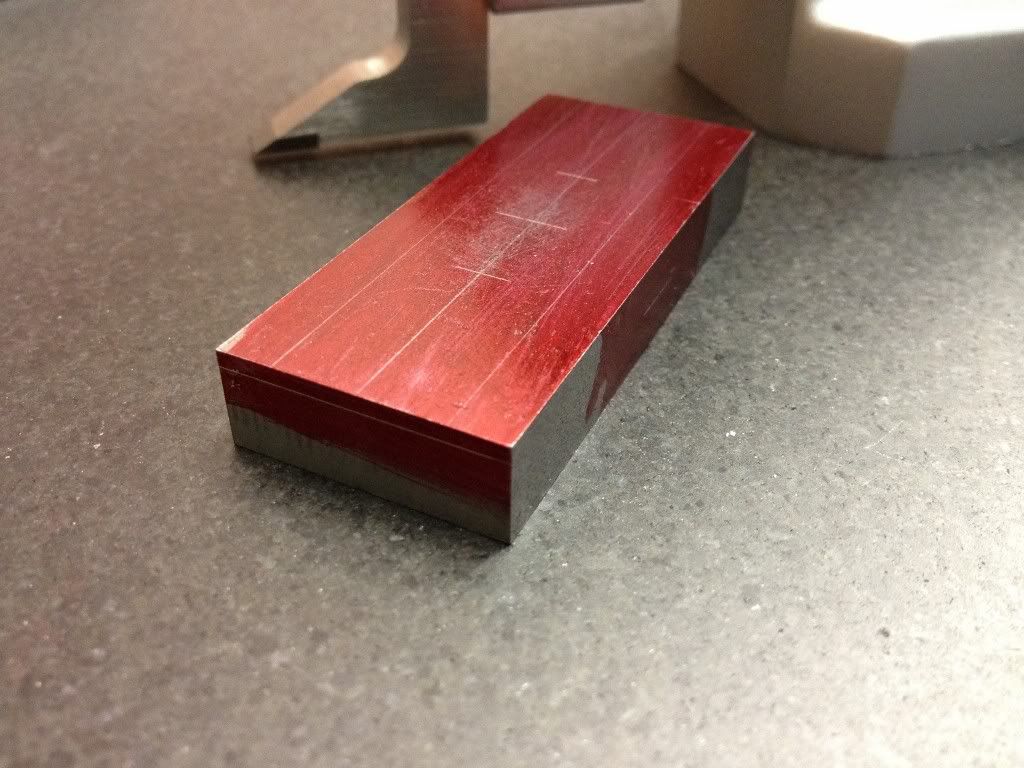
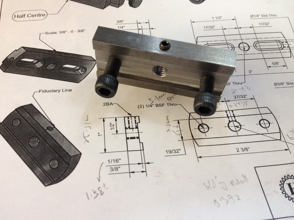
| I pat myself on the back for this part of the job done. |
.jpg) |
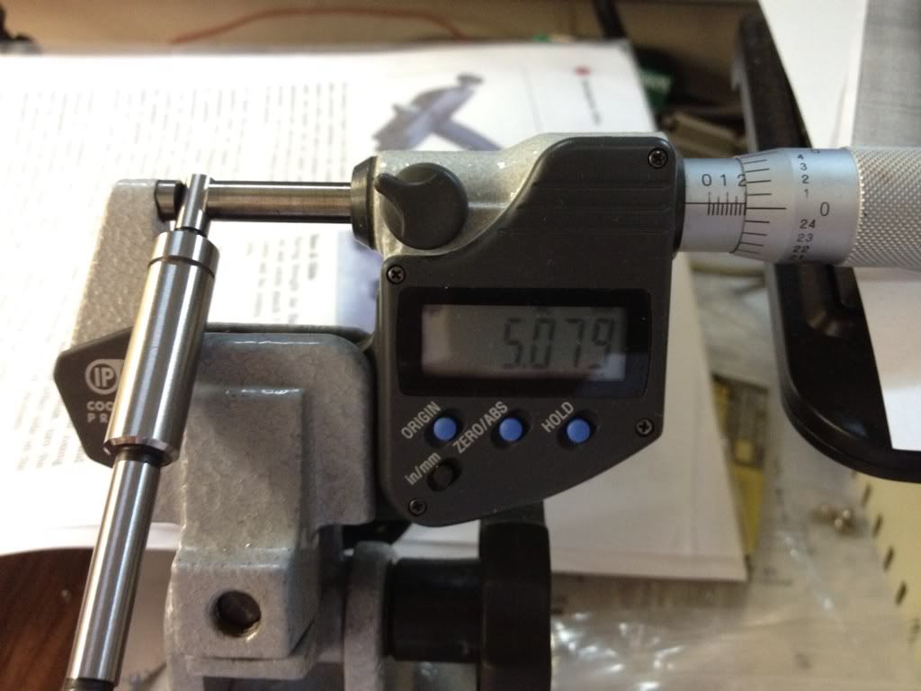
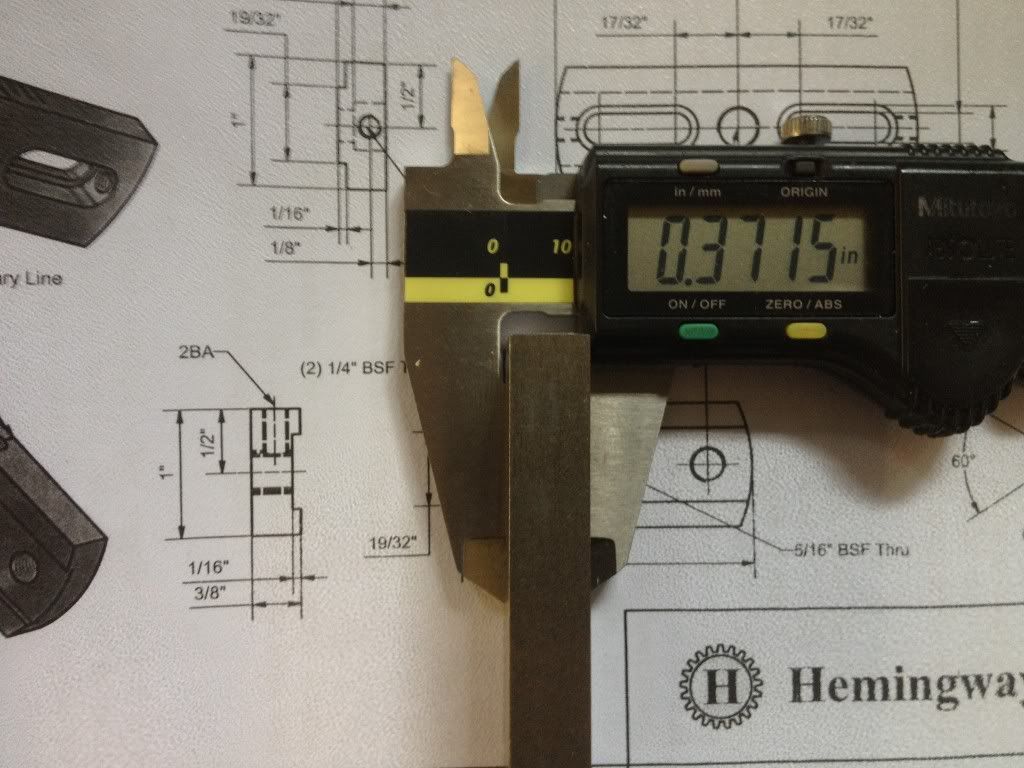
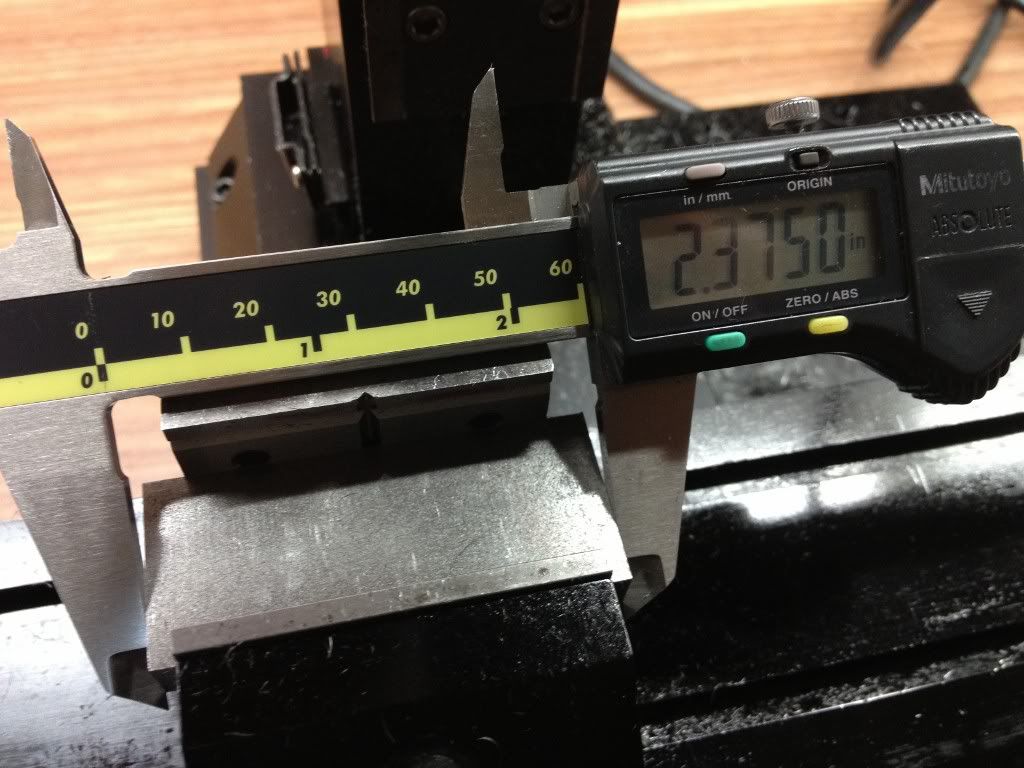
| And a big smile when I measured the OD! |
Its now passed 3am. I've to leave the boring of the bearing mounting hole and the 2 recesses for the flange till the next session. Don't want to be sleeping on the job tomorrow, especially at the wheel. Time to wash up and hit the bed.


.jpg)
.jpg)
.jpg)
.jpg)
.jpg)
.jpg)
.jpg)
.jpg)
.jpg)
.jpg)
.jpg)
.jpg)
.jpg)
.jpg)
.jpg)