Acrylic, or plexiglass, is not a material I often use. I've gotten, so far, from Acrylic Centre at Bras Basah to use for partitioning areas of the bench from flying chips. Lately, as I buy more and more stuff for the shop, I started looking at getting a little more organized.
What I've in mind is a stand of sort for my ER collets. I'm likely to make 2; one for the ER16's and one for the ER32's.
I've been hearing about Dama Enterprise from various people, in particular, Terence. He shared about the level of service he experienced when he was at the Ubi Road shop. Staff are courteous and helpful. They serve hot drinks and snacks (FOC) while you browse for the stuff you need and when waiting for your order to be processed. I didn't go for the food & drinks but I'm still impressed.
I've gotten what I need. Next is to do up the gcode. Hope to have the time to do that tonight.
- Posted using BlogPress from my iPhone
Saturday, April 28, 2012
Thursday, April 26, 2012
Few Things I Bought
I promised myself not to post anymore on the items I bought but lacking any progress in the shop, and to keep my blog from getting stale, I broke it.
Over the week and last, 3 parcels were received:

From Arc Euro Trade: Stevenson ER32 Hex and Square Collet Block, Stevenson Metric 10-20-40 & 20-40-80 Blocks, and the 3MT to 2MT open Morse Tapper Sleeve.

From Chrono: Glanze 10mm Parting Tool with 2 spare blades & Centre Square.

From RS Components: 12mm diameter Silver Steel Rod.
- Posted using BlogPress from my iPhone
Over the week and last, 3 parcels were received:
From Arc Euro Trade: Stevenson ER32 Hex and Square Collet Block, Stevenson Metric 10-20-40 & 20-40-80 Blocks, and the 3MT to 2MT open Morse Tapper Sleeve.
From Chrono: Glanze 10mm Parting Tool with 2 spare blades & Centre Square.
From RS Components: 12mm diameter Silver Steel Rod.
- Posted using BlogPress from my iPhone
Sunday, April 22, 2012
Exploded Diagram of the Half Nut & Apron Assembly
Found the drawing on the Proxxon manual showing the half nut assembly.
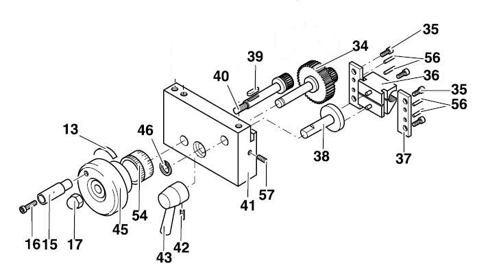
This part of the manual are all in German. Yahoo! Babel Fish was roped in to translate the parts I'm interested in.
P/N
36 - Klemmmutter: Clamping Mother (Mothers that clamped down on kids???)**
37 - Blech: Sheet Metal
38 - Nocke: Cam
56 - Stift: Pin
57 - Madenschraube: Set-Screw
The labeling provided no more insight than when I started. But at least I know that part number 38 is a cam and half nut in German is clamping mother... lolz... just kidding.
** Edit: I found the actual translation on the web after looking at the exploded diagram of the gear train. In the gear train, the square nuts holding the gears were labelled as "Vierkantmutter", which Babel Fish translated as "Square". This leads me to believe "mutter" to be "nut". Therefore, Klemmmutter would be deduced as "Clamping Nut" instead.
By looking at the exploded diagram, I started thinking that I might be barking up the wrong tree. Truth is, from observing that the lead screw shifted upwards when the half nut is engaged, I thought that if I can some how adjust the half nut up a little, I can minimise that movement and I will have lesser of the binding feel when turning the lead screw handwheel. Apparently I'm wrong here. The cam has a fixed position on the apron and the 2 pins behind the half nut have their fixed positions on the cam. These leave me with nothing to play with to solve the problem of turning the handwheel. Till now, the function of part 57, the set-screw, is still a mystery yet to be solved. The fear of stripping its head trying to remove it stopped me from probing further. Could it be the toothed rack that the apron handwheel's gear rides on that needs to be adjusted? What about a bigger handwheel for the lead screw? Would that solve the problem?
Many questions left unanswered. I wonder if I should do whatever adjustments I can to make it smooth enough to go on to my next project or should I probe further to gain better understanding of how things work together. I've not turned the handwheels of another machines other than my own to know if what I have are already normal. Maybe I should hang around some machine shops, make friend with the owners, and request to play with their bigger machines. An owner of a shop on Toa Payoh Lorong 8, which sported some Chinese made, BP look-alike milling machines, seems friendly. I happened to walk past last year after visiting a client in the next block and stood there a about 5-10 mins watching him working on his mill. He turned around, saw me, smile, and went back to his work. I also have a client who owns a manual machine shop in Tampines Industrial Park. May be I can asked him if he is willing to allow me some time on one of his machines; not to do any work but to get a feel of a real machine.
Lathe Carriage: Oops!
I mustered my courage and went ahead to try disassembling all the parts on the apron - the engagement lever, the gears etc. When I'm finally at the real job, I couldn't proceed. The half nut assembly didn't want to come off after I removed the 4 cap screws... Afraid that I may break something if I pushed on, I went on to fiddle around with the carriage gib adjustment which the cap screws and set screws are now accessible. The adjustments were done without the lead screw installed. I managed to get it to the point that the carriage slides easily on the lathe ways with no apparent movement when twisting or lifting it by hands. Some tight spots towards very near to the spindle flange but I don't usually cut that close to the spindle.
With the lead screw installed, everything changed; there was the sound of the half nut rubbing on the lead screw and the lead screw handwheel was extremely hard to turn! While turning the handwheel from the spindle end to the tailstock end, I can feel my arm getting cramp...
I inspected the movement of the lead screw with the half nut engaged and disengaged. There seemed an excessive movement of the lead screw which may explained the problem I'm facing. The 3 cap screws holding the apron was released and tightened again with the half nut engaged. This ease off the tightness a little when turning with the handwheel and the rubbing sound is now gone. But the turning of the handwheel is still not smooth. Help!!! It is now worst than before!!!
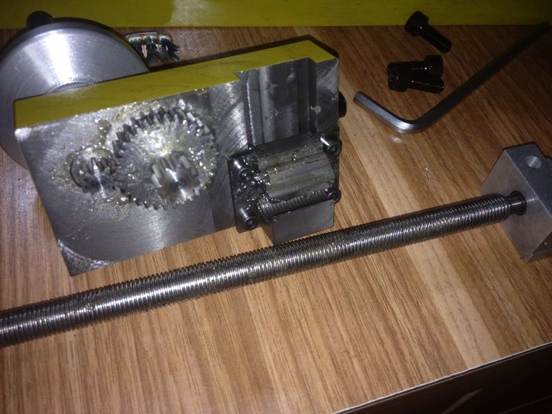
Some pics of the session yesterday and this morning:
I can't seem to do anything further till I figure out how to remove the half nut and so proceeded to put things back.
There are some bit of tight spot near the spindle but that's the best I can do with my current skill level...
The major problem popped up with the lead screw was installed. It was so tight with the half nut engaged that I can't turn the lead screw at all. The 3 cap screws holding the apron to the carriage was loosen, half nut engaged, and tightened again. I did this near the handwheel, in the middle of the way, and near the spindle. Found that doing this nearer the spindle yielded the best result.
Some slight movement can still be seen on the lead screw when the half nut was engaged. Some grease elbow still needed to turn it. This is not to my satisfaction at all.
This video was taken to show the lead screw movement when the half nut was engaged.
If you have any insight on this issue, kindly drop me a comment or send me an email. Any help is very much appreciated.
With the lead screw installed, everything changed; there was the sound of the half nut rubbing on the lead screw and the lead screw handwheel was extremely hard to turn! While turning the handwheel from the spindle end to the tailstock end, I can feel my arm getting cramp...
I inspected the movement of the lead screw with the half nut engaged and disengaged. There seemed an excessive movement of the lead screw which may explained the problem I'm facing. The 3 cap screws holding the apron was released and tightened again with the half nut engaged. This ease off the tightness a little when turning with the handwheel and the rubbing sound is now gone. But the turning of the handwheel is still not smooth. Help!!! It is now worst than before!!!
Some pics of the session yesterday and this morning:
 |
| The half nut engagement lever removed. |
 |
| Apron handwheel taken out to free the gear on the other side of the apron. |
 |
| Removing the key require some care. Otherwise, it may fly across the room and too lost to be found... |
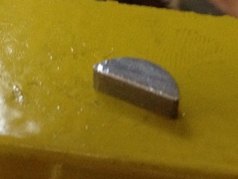 |
| Sorry for the blurry shot. The key didn't fly but I marred its surface a little. A smooth file was used to gently removed the burrs caused by the plier. |
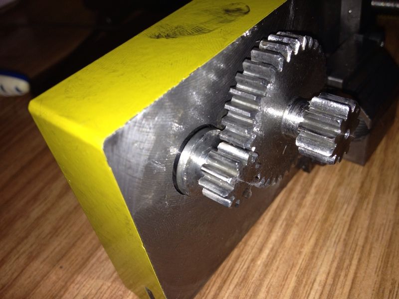 |
| The little gear on the left is what the apron handwheel was coupled to. It can be removed till the bigger one comes out. |
 |
| This circlip is what holding the bigger gear. Even with the circlip plier, it flew to the other side of the shop. I heard it landed and managed to retrieve it - a miracle in my shop... |
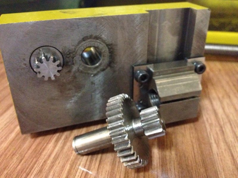 |
| Out came the bigger gear. The smaller one on it is what moves the carriage via a toothed rack beneath the lathe. |
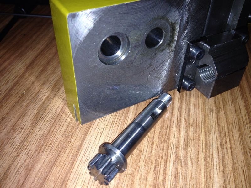 |
| This can now be removed. |
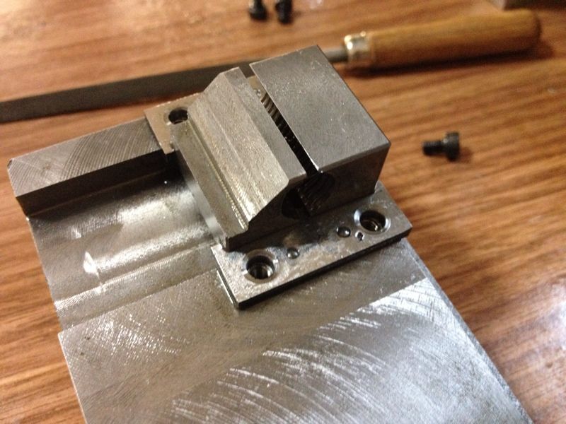 |
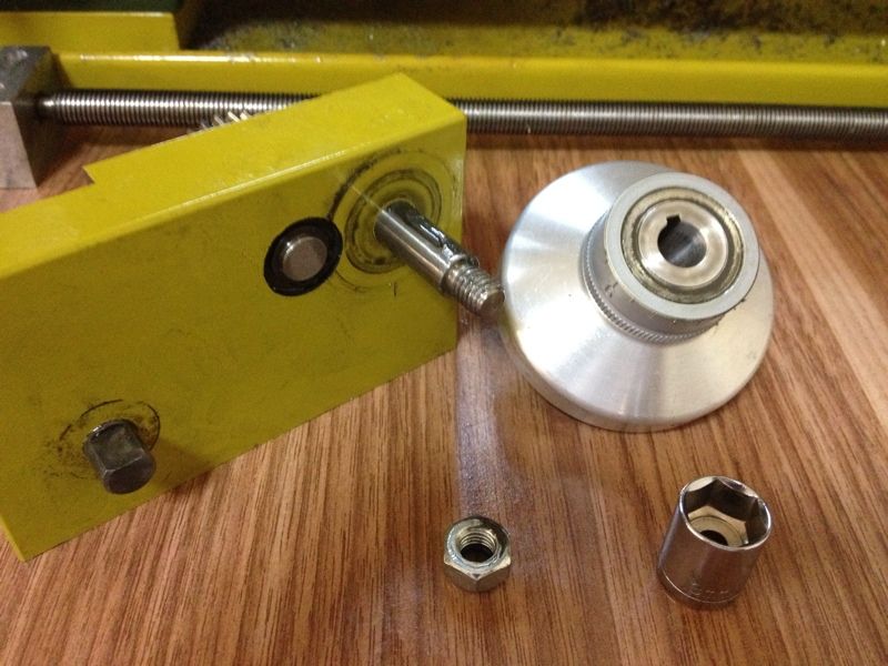
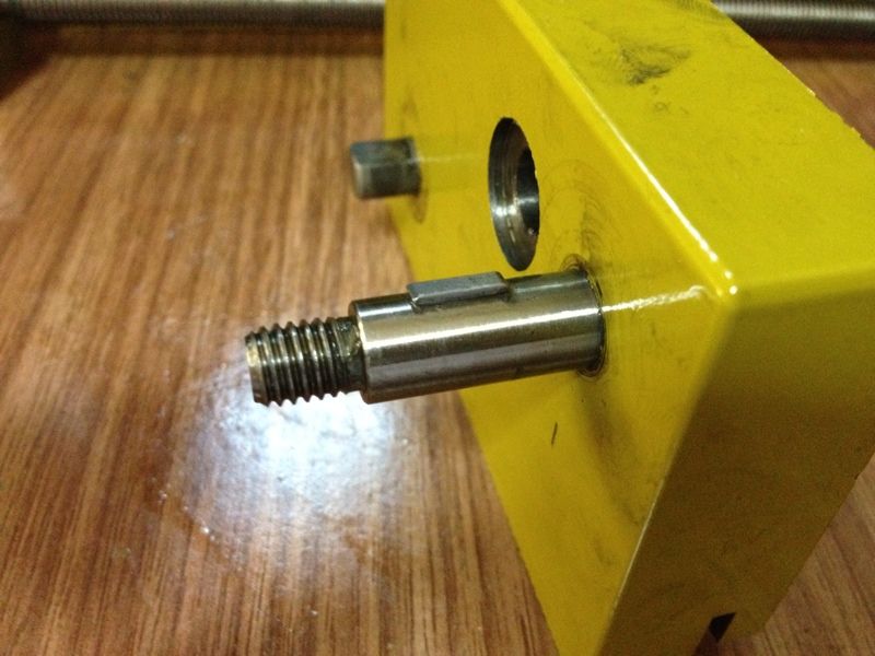
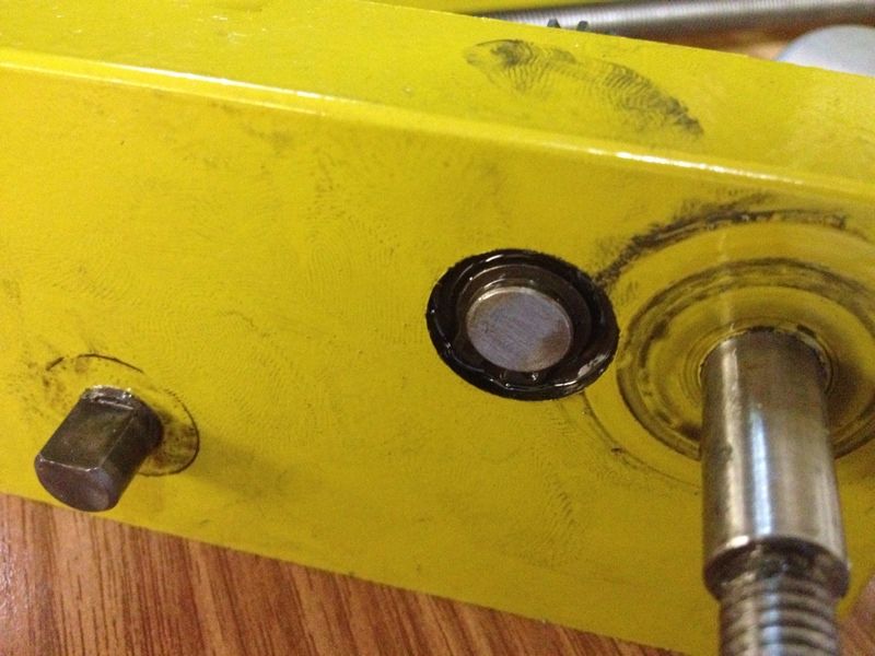
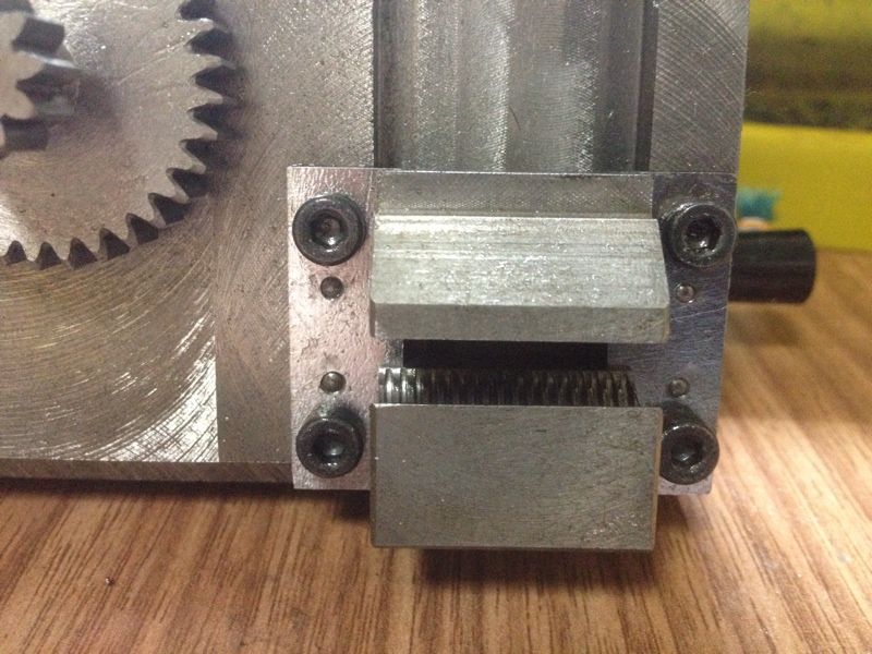
| The 4 cap screws on the half nut assembly removed. I originally thought that these are what hold the half nut to the apron but apparently not. There are 4 pins (2 to each side) between the cap screws. Wonder if these need to be driven out to release the half nut. |
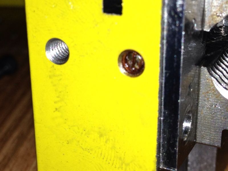 |
| While examining what else can be holding the half nut, I saw this slotted screw on the side of the apron. Could this be the one? I tried removing it but it refused to turn even a little. For fear of messing up the slot on the screw head, I stopped my attempt. |
I can't seem to do anything further till I figure out how to remove the half nut and so proceeded to put things back.
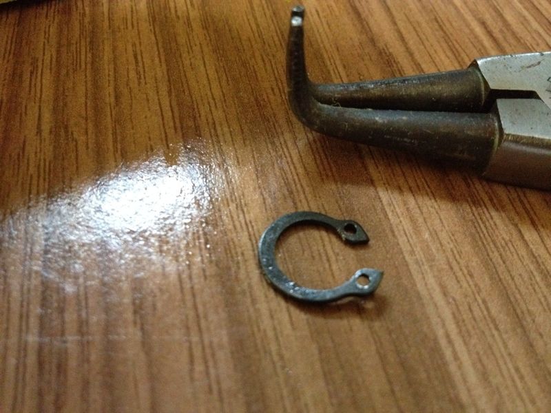 |
| Then I realized that the circlip was bent out of shape... 2 pliers were used to bend it back to close to its original shape. |
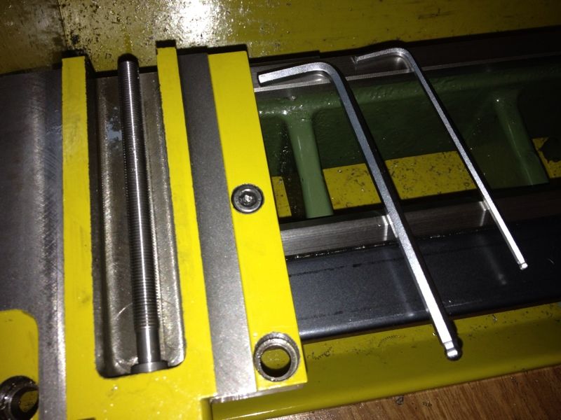 |
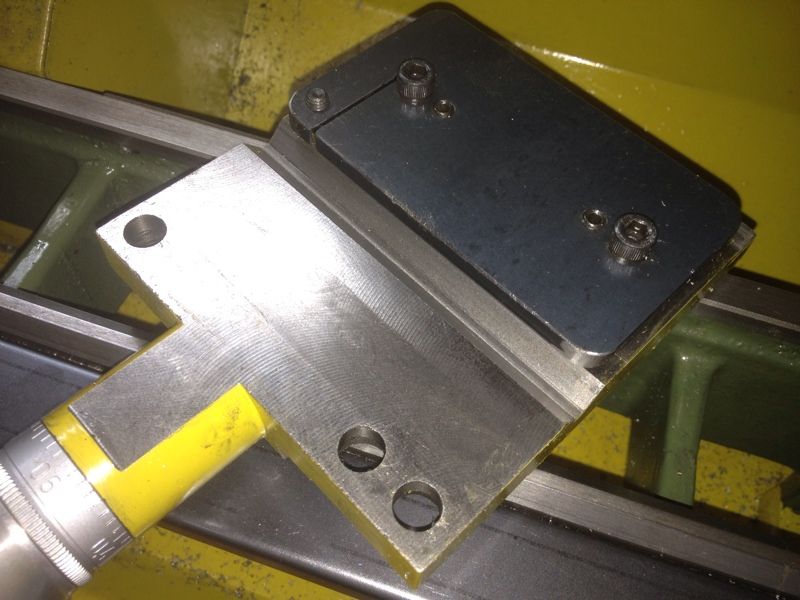
| Before installing the apron and lead screw, the gib plate was adjusted. I found that the metric allen wrenches I bought are long enough to allow adjustments from beneath the lathe. |
The adjustment of the gib plate took me a long time. The cap screws beneathe were tighten enough to hold the plate close to the carriage but still allow ease of movement. The apron was then installed to test and further adjusted.
There are some bit of tight spot near the spindle but that's the best I can do with my current skill level...
The major problem popped up with the lead screw was installed. It was so tight with the half nut engaged that I can't turn the lead screw at all. The 3 cap screws holding the apron to the carriage was loosen, half nut engaged, and tightened again. I did this near the handwheel, in the middle of the way, and near the spindle. Found that doing this nearer the spindle yielded the best result.
Some slight movement can still be seen on the lead screw when the half nut was engaged. Some grease elbow still needed to turn it. This is not to my satisfaction at all.
This video was taken to show the lead screw movement when the half nut was engaged.
If you have any insight on this issue, kindly drop me a comment or send me an email. Any help is very much appreciated.
Sunday, April 15, 2012
Lathe Carriage - Should I or Should I Not?
The slides of the lathe was stripped for some generally cleaning. This time, I managed to remove the carriage which I couldn't previously. This goes to show the more I use the machine, the better I understand it. But my confident stopped right here. I'm deciding if I should disassemble the 1/2 nut for thorough cleaning and maybe attempt some adjustments to make it operates smoothly.
These are the pics taken of the apron and carriage:
So, anyone can enlightened me on the half nut adjustment?
These are the pics taken of the apron and carriage:
 |
| The lead screw has to come out first before I can remove the apron then the carriage. How silly I was before... The air compressor was used to blast away all the chips and the old grease was wiped off. |
 |
| The half nut looks easy to disassemble but I'm concern about not being able to put it back properly with the clutch at the right position. |
 |
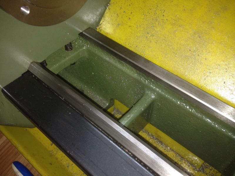
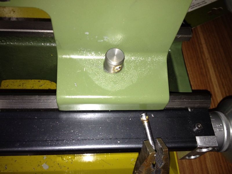
| The bottom of the carriage. The 2 cap screws and set screws were the trouble when I first tried adjusting the carriage from underneath. It is clear from this pic that the carriage lock operates only on one corner of the gib plate. I wonder if it can be easily relocated to the middle. |
 |
| I took this pic to prepare for the making of the carriage stop. With pics in my iPhone, I can visualize how certain things can be implemented while I'm outside. |
So, anyone can enlightened me on the half nut adjustment?
Hemingway Set-Over Centre: Completed!
Or so I'm declaring it to be...
Found some 2BA cap screws yesterday. Poey Huat Hardware has them in steel all along though I was told by one of their staff last week that they only have them in brass. It took the elderly man quite a good 15 minutes to locate the box. Its content covered with rust. He commented that there hasn't been any enquiry on the BA screws for quite a long time. Not very popular in this part of the world. Unfortunately, the plans in those books I bought use them. I'll use the closest metric cap screws when I get started making the tools shown on those plans.
The cap screws are a little longer than required. That's the only box found so I won't push it. Don't think he is keen to sell me 6 screws having to turn the place upside down - I won't...
Here is the pic:
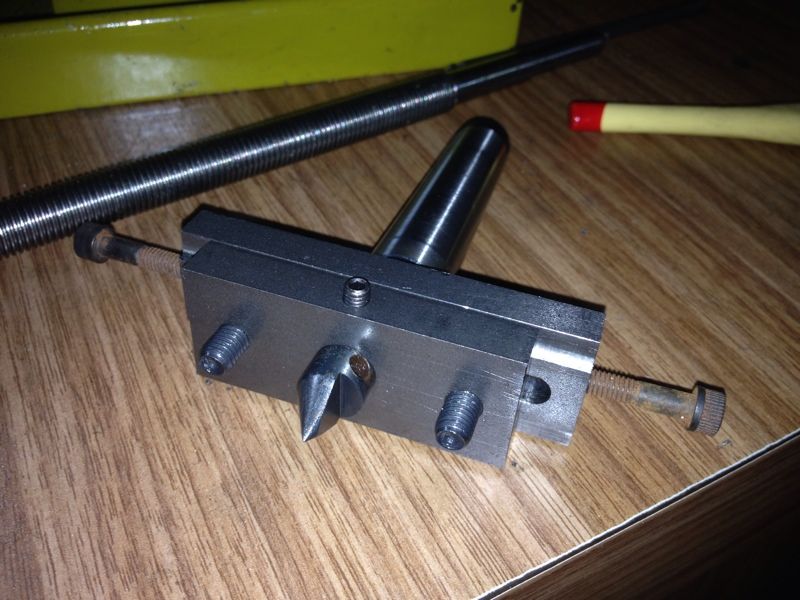
The lathes lead screw can be seen in the background. That's the story for the next post :-)
Found some 2BA cap screws yesterday. Poey Huat Hardware has them in steel all along though I was told by one of their staff last week that they only have them in brass. It took the elderly man quite a good 15 minutes to locate the box. Its content covered with rust. He commented that there hasn't been any enquiry on the BA screws for quite a long time. Not very popular in this part of the world. Unfortunately, the plans in those books I bought use them. I'll use the closest metric cap screws when I get started making the tools shown on those plans.
The cap screws are a little longer than required. That's the only box found so I won't push it. Don't think he is keen to sell me 6 screws having to turn the place upside down - I won't...
Here is the pic:
The lathes lead screw can be seen in the background. That's the story for the next post :-)
Wednesday, April 11, 2012
Hemingway Set-Over Centre: Checking Centre Height
This is a short post for GeneK :-)
I didn't really make sure that the top edge of the Set Over Centre is parallel to the bed. It was set by eye-balling. Should be alright.
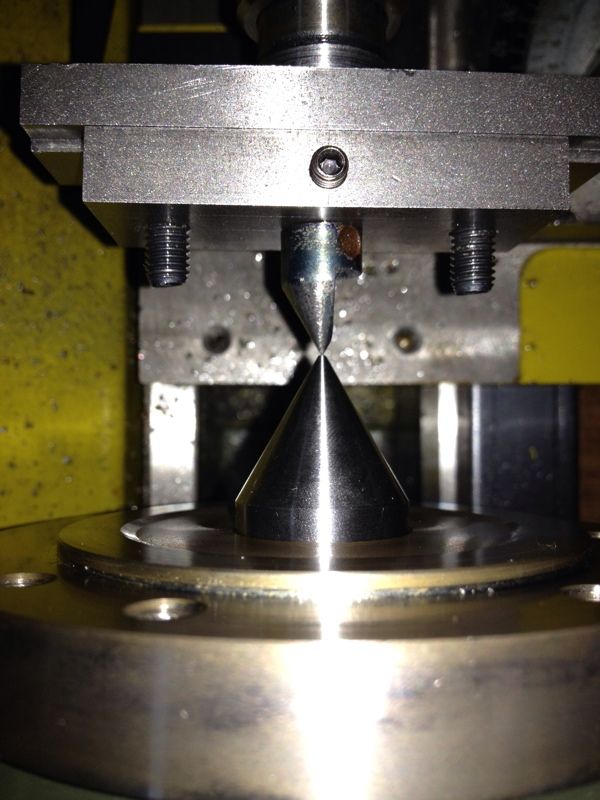 |
| From the top. Of course, adjusted true using the Slide. |
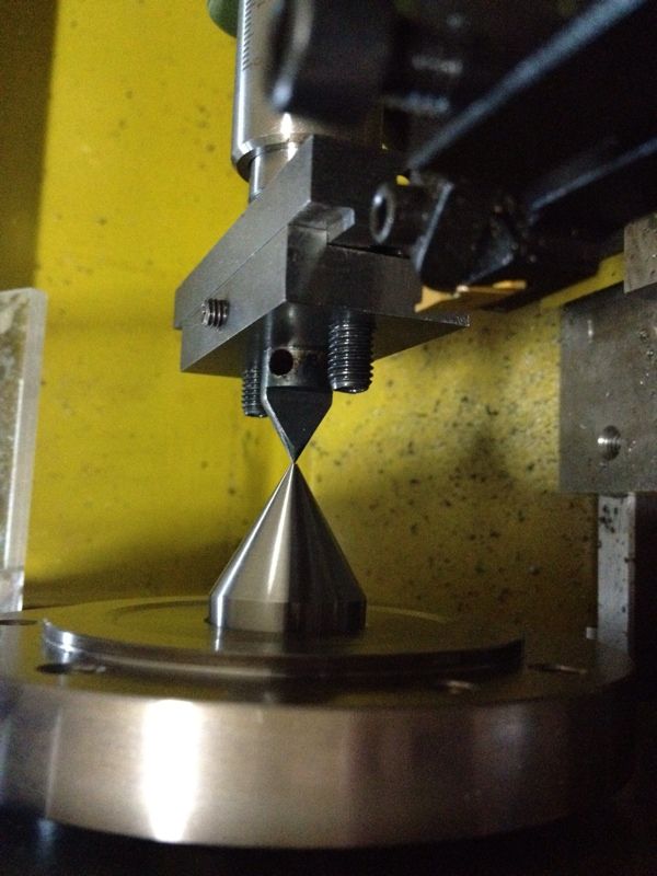 |
| From the side. Not really a perpendicular shot. I think I got it very close to the right height. |
I didn't really make sure that the top edge of the Set Over Centre is parallel to the bed. It was set by eye-balling. Should be alright.
Sunday, April 8, 2012
Hemingway Set-Over Centre: The Arbor - Completed
I don't really have a good feeling of what I'm doing on the arbor. There was slight wobbling when the lathe was powered on. I pressed on with the job despite that. The morning session ended when I was at the threading part as I encountered difficulty to start the die cutting. I bought the Proxxon Tailstock Die Holder from Mike and my dearest collected it for me in the afternoon while I was at work at a project called The MeyeRise.
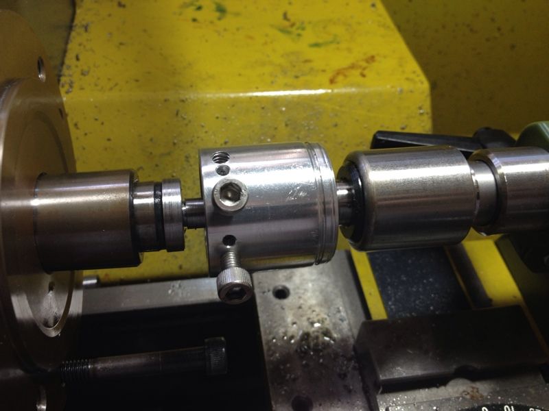
The completed parts so far on the 2MT arbor installed in the tailstock:
The rest of the pics described what I did in 3 sessions.
The completed parts so far on the 2MT arbor installed in the tailstock:
 |
| The 2 cap screws have yet to be trimmed flushed. |
 |
| Before I started work on the Arbor, I removed the locking screw I made for the tailstock as I couldn't get it tight enough at times and couldn't release it after tightening. Heat was applied to removed the little handle. |
 |
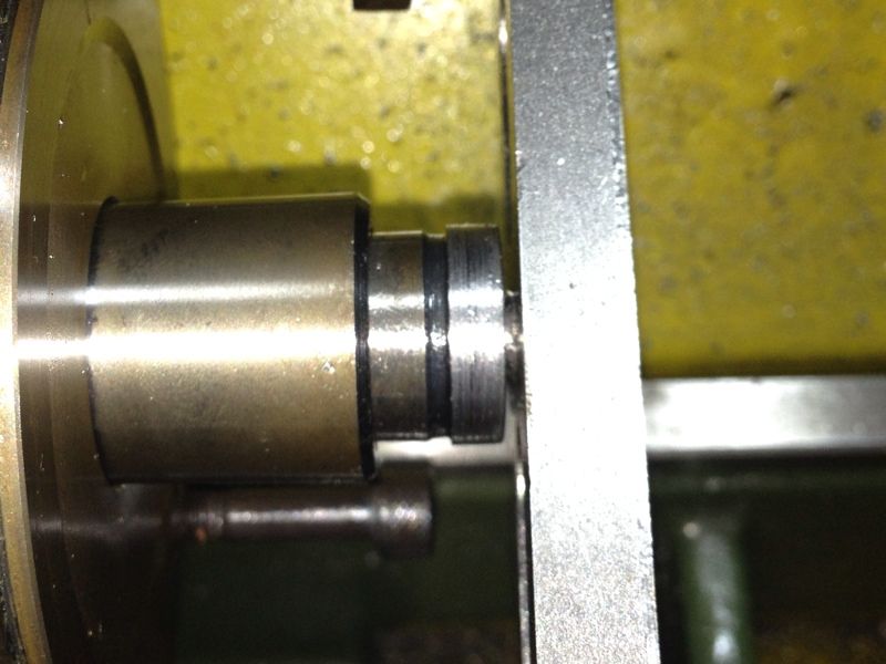
| With about 3mm diameter left to turn down, I decided to try turning between centre to see if I can enhance the concentricity of the business end. The sleeve was taken out of the spindle bore and I realized that the arbor was stuck in it. Will think of how to get it out after I completed this part of the job. |
 |
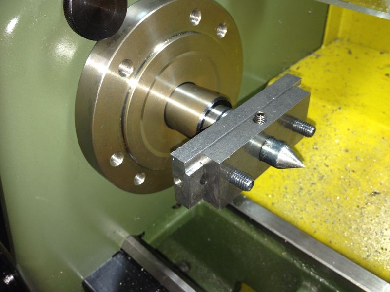
| The Proxxon Centre Turning Accessory put in use. The round aluminium disk acts like a dog driving the job. |
 |
| Too much pressure on the tailstock causing excessive heat. The grease was boiling, darkening the end of the section I was working on. |
 |
| One thing I like about working between centers - I can remove the work and put it back without losing my reference. The workpiece was taken out to clean off the burnt grease and reapply fresh dose. This time, I went easy on the tailstock when applying pressure. |
 |
| After turning down to the required diameter, I tried parting off the excess with the sleeve back in the spindle bore. It didn't work. I can feel the job flexing away from the parting blade. |
 |
| The spindle guard was removed and the hacksaw drafted into service. Thank God I've only about 7.9mm diameter to saw through. |
 |
| Some extra was left to clean up to length. |
 |
| Facing done and sharp edges deburred with a file. The shoulder was also faced making it nice and flat. |
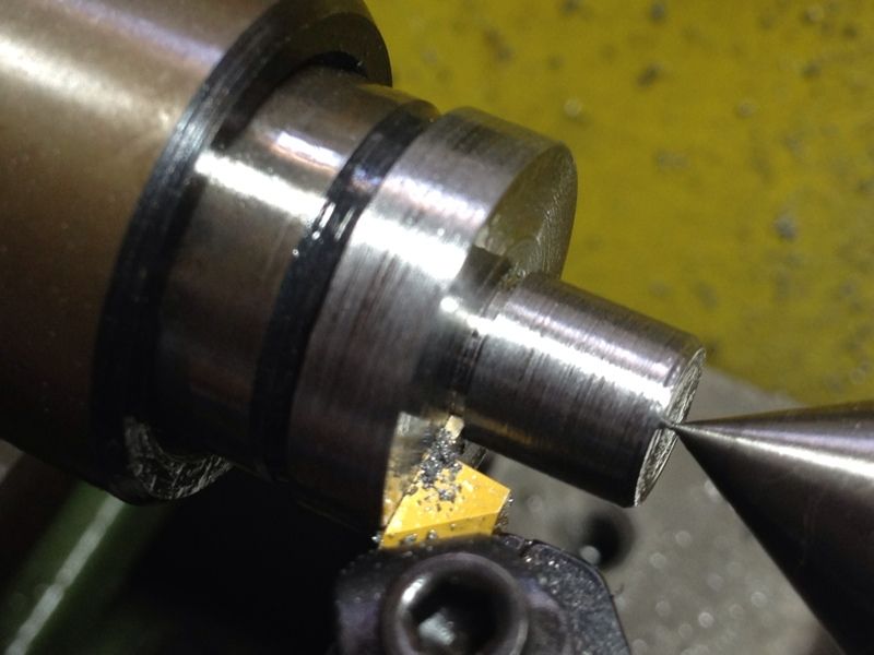 |
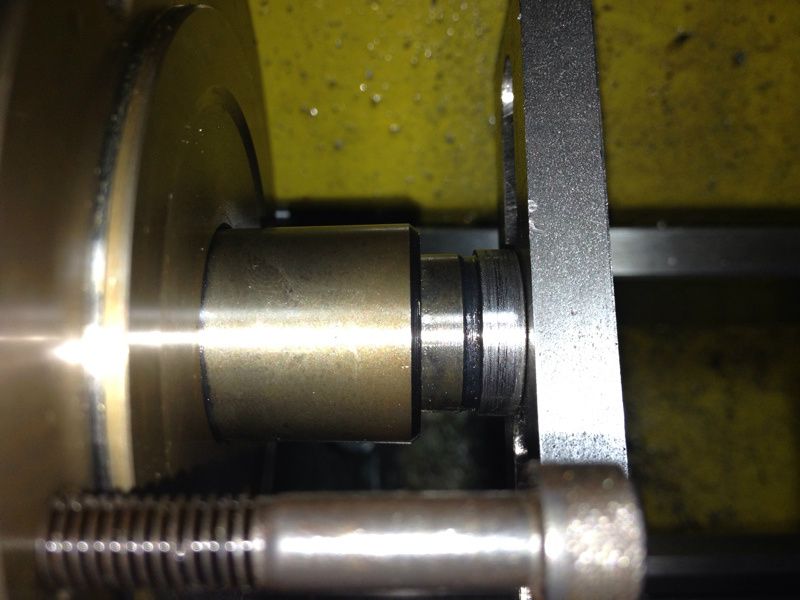
| Sherline's grooving tool in use. I find it rather expensive but it has proven itself to be a very useful tool. The groove created is the undercut for the threads. The live centre was only pressing against the stock lightly to keep the job in place. |
 |
| Trying to employ the same method of cutting the 5/16" BSF threads using the die holder I made for the Sherline Tailstock. It didn't seem to work this round, prompting me to get the Proxxon Die Holder set from Mike. Too many other things I want to do then making a die holder set at this moment. I may make a tap holder instead. |
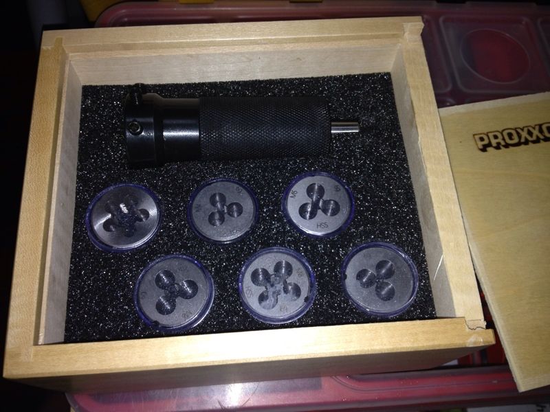 |
| The Proxxon Die Holder Set. I supposed the sliding arbor, which has a parallel shank, is to be held in the drill chuck. |
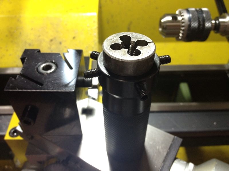 |
| I was rather disappointed that the 5/16" BSF die, which has a diameter of 1", couldn't fit the die holder. All set screws were backed off. I even tried compressing the split die with a plier... sigh... A quick measuring of the Proxxon dies indicated that the die set that came with the box is a little smaller than 1". Why?! |
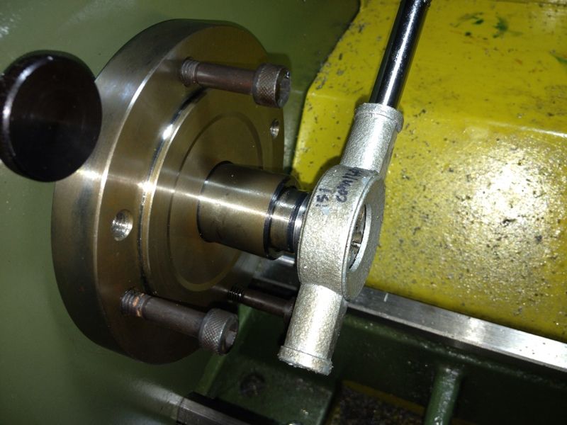 |
| So I pressed on with what I was doing prior to trying the Proxxon Die Holder. The 3 M6 cap screws were used as grip while turning the conventional die stock holder. Hope they wouldn't damage the threaded holes for mounting chucks and other accessories. |
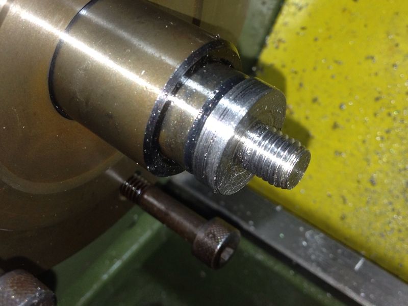 |
| Threading completed. I had to cut away the half formed thread near the shoulder to allow the Base to go all the way in. |
 |
| Even that is not enough. More were cut off to allow a good fit. |
 |
| And finally... |
 |
| The whole works on the arbor. Next is to find a way to get the 2MT arbor out of the 3MT sleeve. |
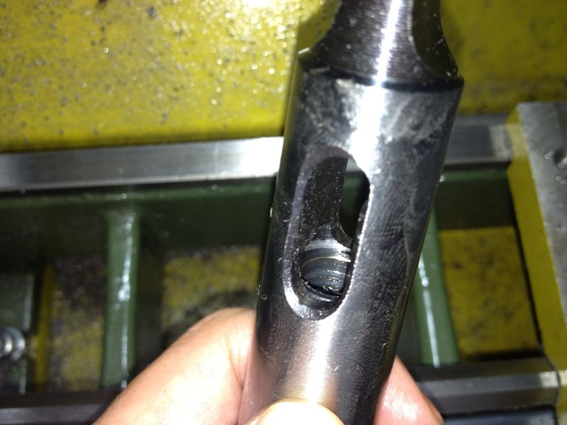 |
| The threaded end of the 2MT arbor is just a tad lower than the slot for easy knocking out with a wedge tool (I don't have one anyway...). |
 |
| The 5mm Allen key and a small hammer did the job of breaking it free. |
 |
| Though still short of the 2 adjustments screws, a group photo of its members so far doesn't hurt. |
I'm getting excited as I'm coming to an end of this project. Wanted to buy the 2 x 2BA screws but the shop I always frequent only have them in brass. Maybe that will work. Should have buy them to test than merely walking away disappointed.
I've yet to test if the centre lies up with the centre line of the lathe. Feeling exhausted from the long boring showflat duty I was scheduled this afternoon, I decided to stop work, wash up, and do some reading before bed. Got to get up early for Resurrection Day service tomorrow morning. It is the most important day in history of mankind.
Monday, April 2, 2012
Hemingway Set-Over Centre: The Arbor
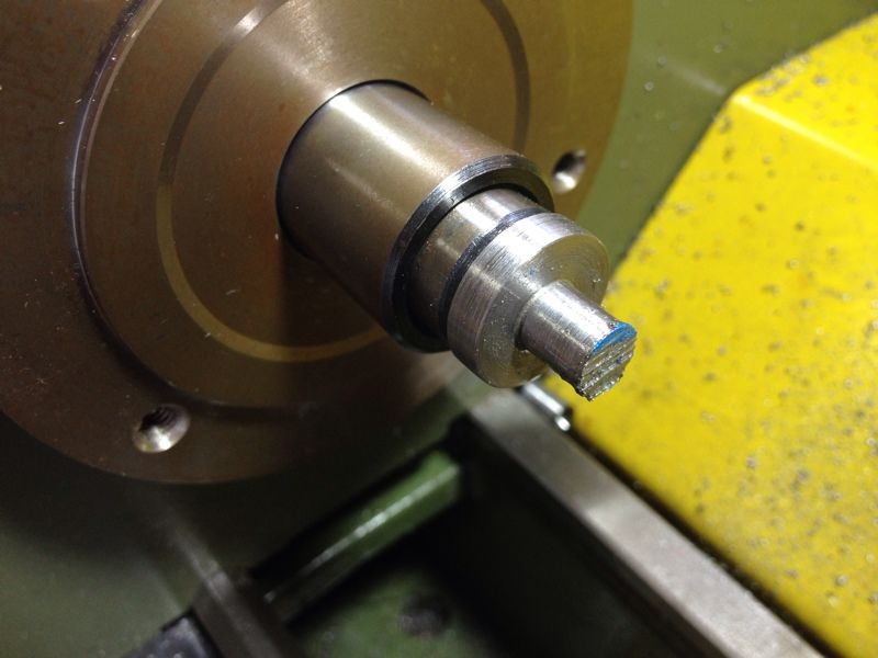
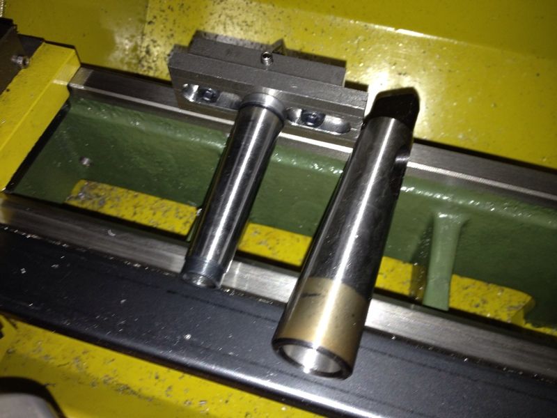
Work started yesterday evening machining the soft end of the supplied 2MT Arbor. The job is to turn down a 5/16" section and put on the 5/16" BSF thread to thread the Base on.
 |
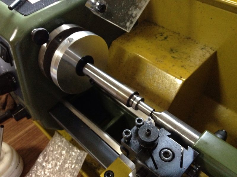
| The 2MT arbor was fitted on a 2MT to 3MT adapter sleeve for the spindle bore. The "soft" end measured 1" in diameter. The first job is to turn this down to 3/4". |
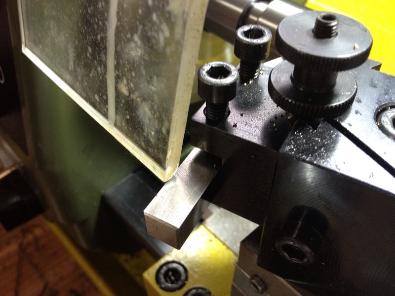 |
| Realised that the cover blocked the carriage as the Proxxon tool in use is too long. |
 |
| Using the handle of the chuck key to lift up the cover a little to clear the tool. |
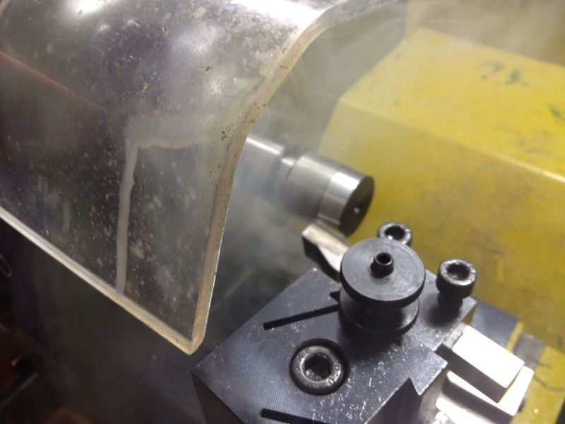 |
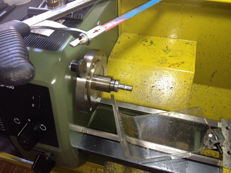
| Lots of smoke produced during cut due to the cutting oil. Hope no one call the fire department... |
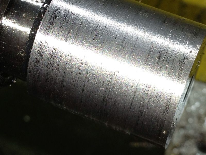 |
| Surface finish was rather bad when I stop to inspect the job. |
 |
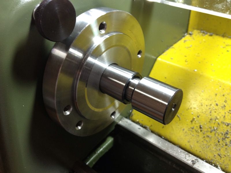
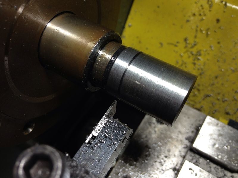
| As advised by the good folks of Metalworkingfun.com, I swapped in the Sherline's carbide insert tool for its radius tip and started turning at 0.1mm per pass. |
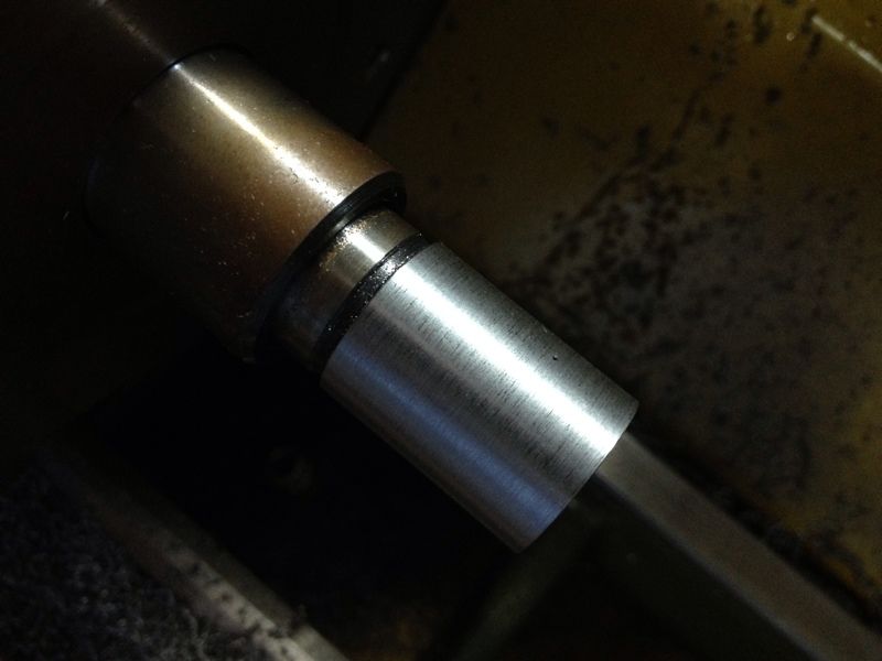 |
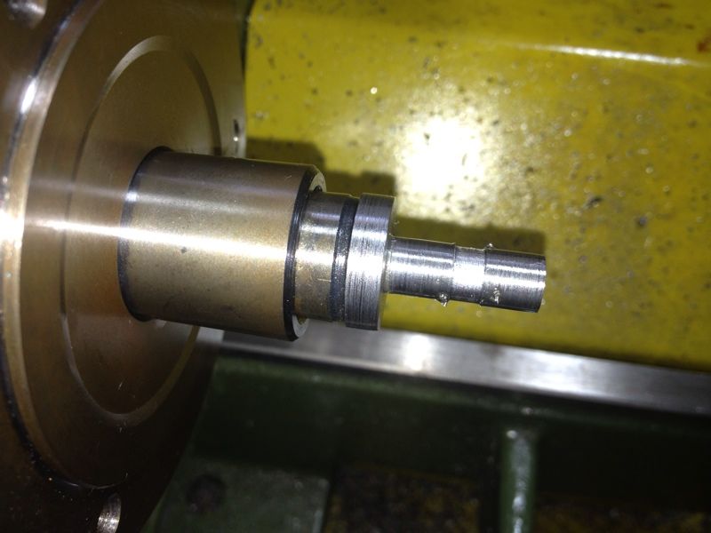
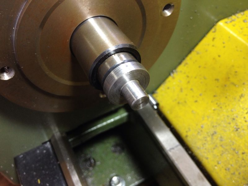
| So much better... The 3/4" diameter done. The left end of the job measures exactly 19.05mm (or 3/4") while the right end 19.03mm. |
Next is to reduce a section down to 5/16" leaving 3/16" length of the stock at 3/4". In order to know which I should stop turning, I tried cutting a groove but parting this material turned out to be rather unpleasant. The AR Warner's part-off tool just jammed mid way through the cut. But what was done provided sufficent visual of the stop point.
 |
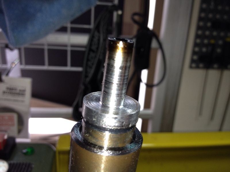
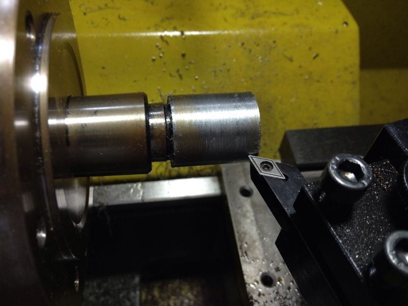
| Wanted to cut to the diameter of the tap drill of the 5/16" BSF thread, which is about 6.5mm, but the part off tool kept getting jammed up during cut. Only managed to about 2mm before giving up. |
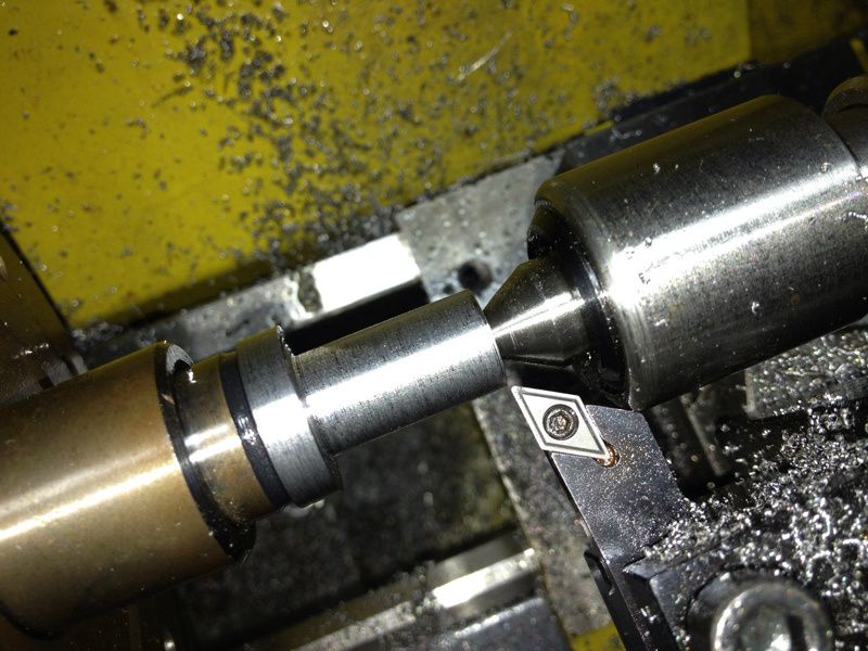 |
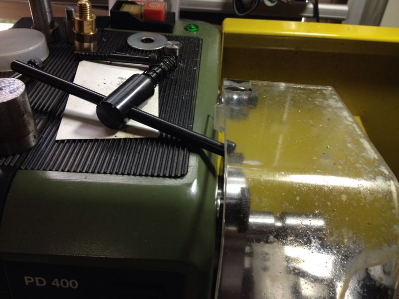
| Turning down till the tool was blocked by the body of the live centre. Looks like I've to get another live centre but with longer nose to avoid this problem. Meanwhile, I'll adjust the angle of the quick change tool post (QCTP) to allow the tip of the tool to go further in. |
I'll continue with the arbor in my next session. Long day tomorrow with appointments covering the first 3/4 of the day.
Have a blessed night.
Subscribe to:
Posts (Atom)