The stock was cut almost to length on the bandsaw and trimmed to 3" as called out in the plan. This is the 2nd time I'm hitting the exact dimension - a real boost of confident. Wishing for more as I progress...
 |
| Redoing the drawings with the bottom right corner of the workpiece as datum. |
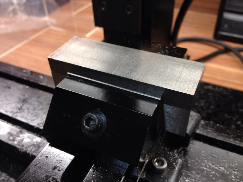 |
| The stock was held in the vise and carefully tapped down to ensure full contact on the parallels beneath. The layout lines can be seen in the pic. No punch mark this time as advised in the forum. |
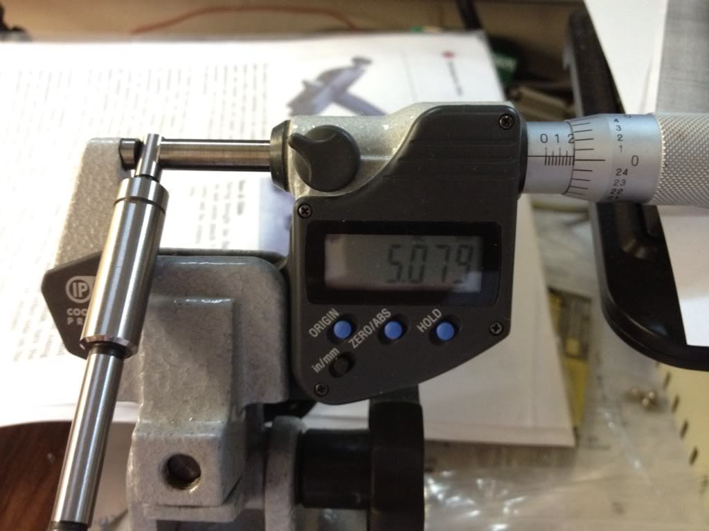 |
| Measuring the tip of the Proxxon Edge Finder. It actually measures 0.2", kind of strange from Proxxon which has everything else in metric. |
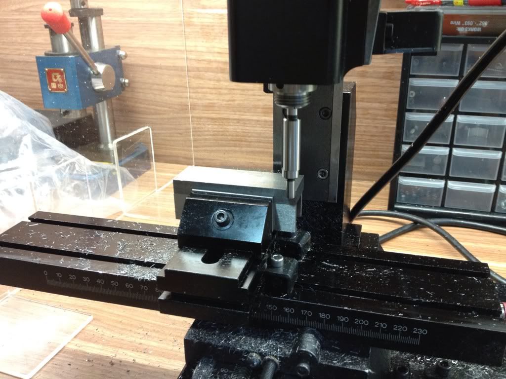 |
| Finding the edge in Y axis. The table was moved over by half of the tip of the Edge Finder to zero the spindle axis to the edge of the workpiece. X was next. |
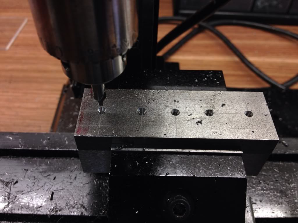 |
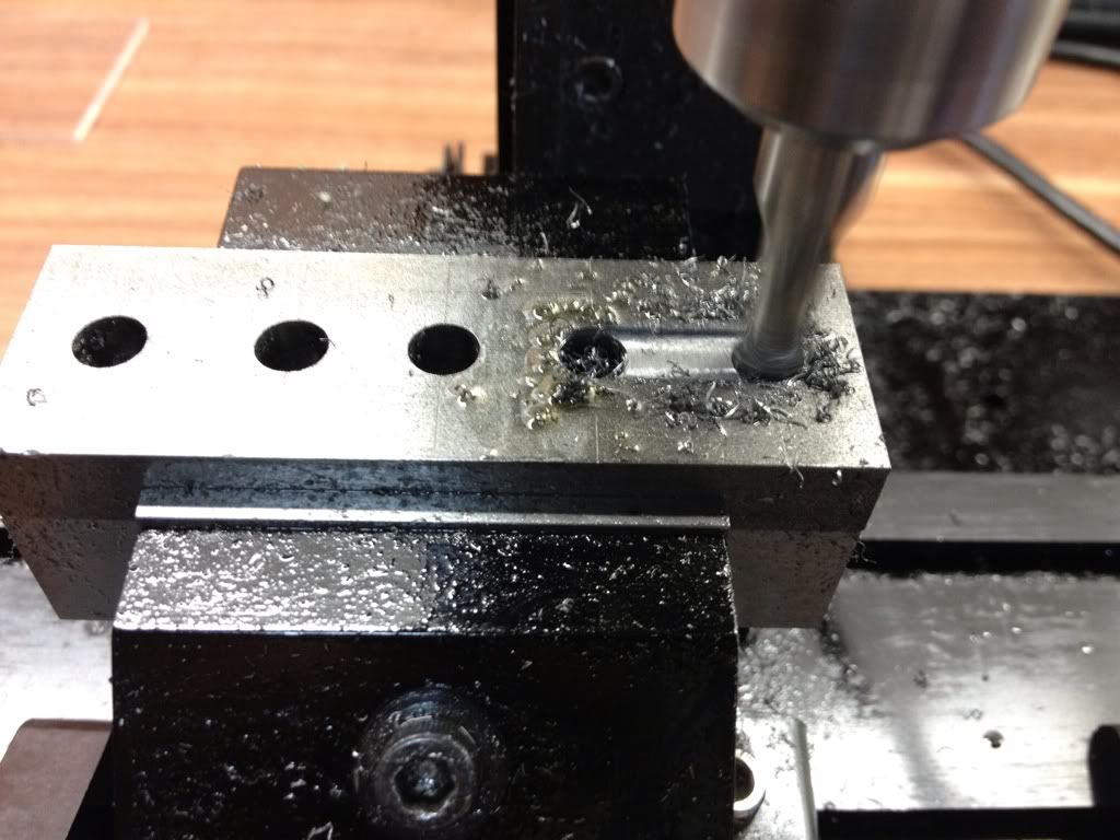
| Centre drilling of the 5 holes for later operations. This is the first time I centre drill all the holes before drilling. I always like to centre drill and drill through each hole before moving to the next location to reduce the number of times I have to move the table (and save on counting...). |
 |
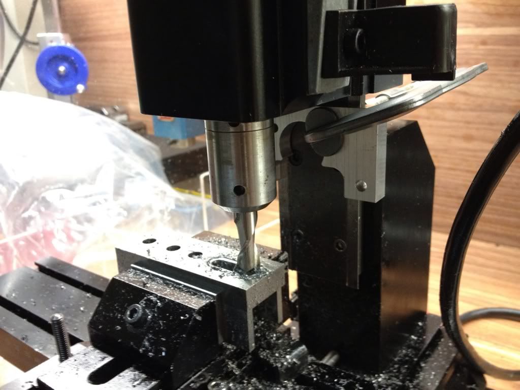
| Drilling the holes using 1/4" drill. |
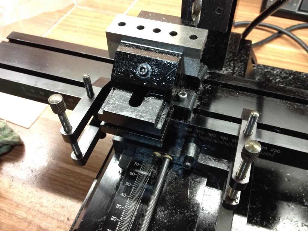 |
| A pair of machinist clamp was deployed as limits for the slot to be milled. There are 2 slots in this part; one connecting the 2 holes on the right and the other, the last 2 holes on the left. This will save me from having to count the number of turns I've made to focus on the job at hand. I plan to make mill stops in the near future for all 3 axes to ease the process. |
 |
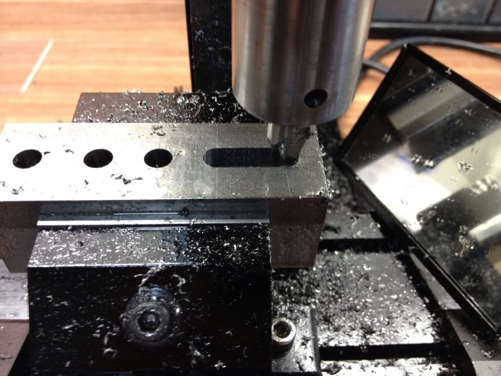
| Begin milling the slot with a 1/4" slot drill (or 2 flute endmill as the American call it). I started with depth of 0.2mm per pass but went on to 0.5mm. |
 |
| Slot done. The 3/8" slot 1/4" deep was next. |
 |
| A piece of scrap used as depth stop for the Z axis. Wanted to use machinist clamp for this but I couldn't locate the other 2 pieces I bought. |
 |
| Done! Time to test if the cap screw will fit. |
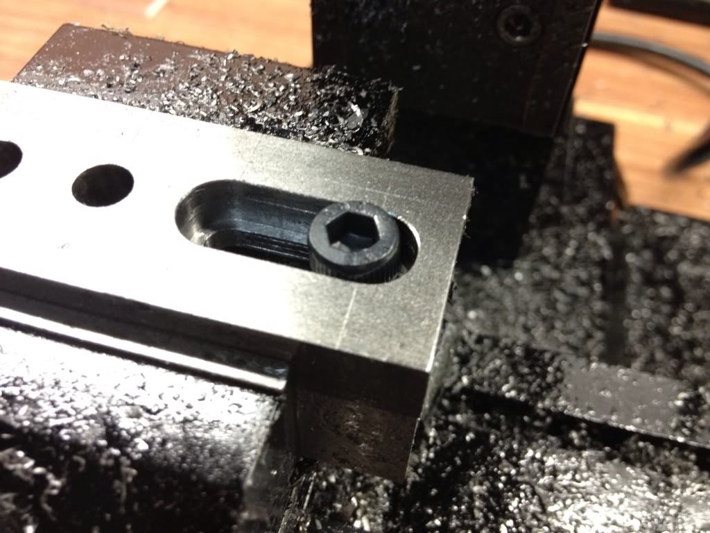 |
| Unfortunately not... The supplied 1/4" BSF cap screw's head measures slightly larger than 3/8" and the 3/8" slot drill from Sherline cut the slot at 0.372". The 0.372" seems to be consistent with the slot I did in the Slide before widening. I should be buying another one locally for further testing. |
I left the setup alone when I ended the session. A trip to Chan Man Lee is necessary to get a new piece of 3/8" slot drill and probably another 4 machinist clamps of the same size as the current ones. I may have a problem using the machinist clamps as stops for the Y axis as I'll have to clamp on the dovetail. This may deform the dovetail, which is aluminium. Maybe my next project should be making proper stops for all the axes. If anyone has a good set of drawings of mill stops for Sherline Mill, please share them with me. Meanwhile, I look at JerryG's for the lathe. The concept should be the same.
Till the next session, be blessed.
No comments:
Post a Comment