Monday, December 13, 2010

A2ZCNC Leadscrews upgrade - The Shipment

Just when I thought I could only receive the shipment after my trip to Hong Kong, it arrived in my office today morning.  Took the chance to swing by to pick it up while going to 313 in Orchard Road with the family and mother-in-law.  The well packed box was sitting on my desk awaiting my arrival.


Well padded. No loose parts moving around in the box during the ride back.
After peeling off a thick layer of "onion skin", here lie the contends

The tubes are for the precision leadscrews.  I'm impressed! The screws I bought from Sherline were merely wrapped in brown papers.  Guess the price paid made the difference.

The rest of the parts out of their boxes.  The tube on the lower right is the Way-Oil.  The Gibs were said to perform better than the stock ones.  Both recommended by Tim of A2Z.

Anti-lash Nuts.  Spring loaded to take up backlash.  Some parts look a little worn.  They may be just tear-out, inflicted during testing.  Hope they work fine.

3 views of the saddle.  Look SOLID.  The blue colored strips are of the same material as the ones on the Gibs.


The adapter for the stepper motor mounts.  3 were provided of which 1 was given free of charge.  May not be using it on the Z-axis as that may require me to change the dimensions of the mounting driving the Z-axis saddle.  The plans were downloaded from Graham of Sherline Group.

I'll be leaving the country for the next 4 days starting tomorrow.  Hope to have sometime during the coming Saturday to install the precision leadscrews on the X and Y axis.  Z will have to wait as the backlash nut mount has to be fabricated first.  I'll be away again next Monday and Tuesday.  So little time yet so much to do.....

Tuesday, December 7, 2010

New Tools

I've been shopping online recently.  Including the outlay for the coming holiday, I'm over budget. But... I'm happy :)

Three of the five shipments came in last week, while I'm away in Melaka, Malaysia.  Took some photos to show off here.  The fourth shipment, by far the most expensive of the lot, is on its way.  Hope it reaches me before I take off to Hong Kong for my family holiday and at the same time, to pick up my fifth purchase.

So, what did I buy exactly?

ER16 Adapter with 3/4-16 threads. This is from Carter Tools.  Good support and prompt replies.  Very pleasant experience dealing with Carter despite the low priced item.

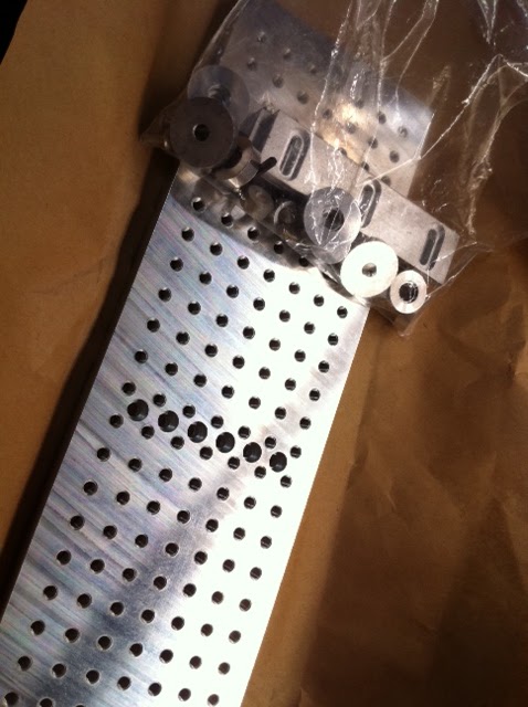
Precision Tooling Plate from High Tech Systems. Mounting holes and the slots at the back need deburring. Derick has also been prompt with his support.
Deburring the mounting holes with a countersink bit. No many holes.  So not so bad.
ER32 (per review on CarterTools.com) collet chuck from Beall Tool Company.  Ordered as a set with some imperial collets with a set of nice looking brass hinges for a good friend of mine.  Not much of a service to talk about as only one of my questions was answered.  Couldn't tell me if its really an ER32.
Front view with a collet mounted.  Look at its size relative to the lathe spindle.  It is mounted on the lathe with the 3/4-16 threads.  Have not tested the run-out.  Maybe after my holiday.
The fourth shipment contains the precision leadscrew upgrade for all my axes on the mill.  Tim of A2ZCNC has been rather helpful with my questions.  The order includes the 3 leadscrews, 3 anti-lash nuts, a saddle, and 3 gibs which Tim said are more superior than the stock gibs from Sherline.  Bought a bottle of #2 Way Oil which was said to be a better lube for the moving parts.

From the installation manual I downloaded, X and Y upgrade look simple enough.  Z requires some modification to make it work.  Tim was kind enough to throw in the adapter to offset the stepper motor mount to fit the new leadscrew.  I'll need to fabricate the mounting required to move the axis.  Plans and photos are downloaded from Graham of Sherline Group.  Hi Graham, thanks for the idea and plans!

The last purchase will be picked up from CTC Tools' office in Shatin, Hong Kong.  This will be my 3rd purchase from Haine.  This round 19 pieces of ER32 collets (metric) from 2mm to 20mm, a 2nd digital dial indicator (1" travel) to make my very own tramming tool from Bogstandard (John) build log on Madmodder.net, and a set of inside/outside radius gauge (1mm to 6.5mm radius).

Come to think about it, I've been buying but have not been building much things.  Need to have that in my new year resolution; to build more stuff and cut down on spending (though I enjoy buying... good form of stress release).

That's all for now, little one needs her milk and daddy is going to make her a bottle...

Sunday, November 28, 2010

3D Milling of a human face

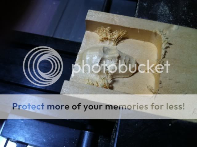
I've been wanting to do this for a while after my first failed attempt. Though I've not been into my shop for quite a few weeks, some time was spent on my notebook applying different features to the 3D head forwarded to me by jrmach of Bobcad forum.  The object is not to mill out the whole head, which I do not have the necessary knowledge at this point to use the 4th axis correctly.  It is to have a go with just the face.  The decision is to only mill out the 1st 10mm from the tip of the nose to experiment with the different features provided for in BobCadCam.  The Z-Level Rough was use to remove bulk of the material (wood this time for ease and speed of the job) followed by Slice Planar.  Cut amount in Slice Planar was set to 0.2mm to try to capture as much details as possible but I'm not able to match up with a smaller diameter cutter; A 6mm ballnose was used with 3mm radius.  Roughing was done with a 1/2" endmill.

Some pics:

Roughing out with 1/2" endmill


After finishing off with the 6mm ballnose

Short video showing the 6mm ballnose at work:


I notice during the milling process that the spindle was almost at the end of the Z travel. It was scaringly close.  Thank God that I decided to go only for 10mm from the surface (z = 0).  Can't imagine what will happen to my mill if I went for 15mm...  I've ordered a precision toolplate with cam type fasteners from Hightech Systems.  This will raise up the work by the thickness of the plate.  From the vpost tracking, it has arrived in Singapore yesterday and should be delivered to me on Monday.

A short video of that:


I also ordered an ER32 holder, some collets, and an ER16 (3/4-16) adapter with this shipment.  Hope these are the last I bought for the hobby this year.

Sunday, November 7, 2010

8-Direction Vertical Milling Column Upgrade - Done!!!

Little time in the shop resulted in no updates for the past weeks.  With the market slowing, I don't know why I'm still so busy.

The column upgrade was finally completed with slight modification to the length of the leadscrew.  As mentioned in my previous post, rotating the circular clamping disk didn't allow the vise to clear the disk.  I bought the column spacer to provide the clearance required.  But the spindle is lifted so high that it couldn't get down low enough to do any useful work.

This seems to be the max the spindle can go down to.

I saw that the leadscrew's end was "tucked" inside the clamping disk and realized that I need to shorten the screw a little.  So out came the Proxxon vise.


Sawing off a short section of the leadscrew.

A little too short but its working fine

Tramming came next.  Roughly getting into position:


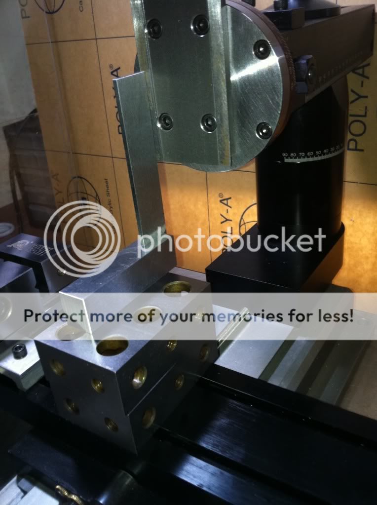
Using DTI to get the column square to X and Y axes:

The rectangular piece is the Proxxon parallel

Best I can do for this

After tramming, I tried to "flycut" with an endmill held in the ER16 collet.  The result was good as I can get to 2 decimal places accuracy (in mm).  I've never gotten so close.  Rather happy with the result of this upgrade.  The 8 direction column makes tramming much easier than my previous setup.  Should have bought the 2010 mill right at the onset.

Further milling revealed that I may have a problem with my mill slipping out of the ER16 collet during cut.  I changed to an endmill holder and the problem went away.  Need to solve this as the ER16 way of holding tools is the most convenient to me.  Anyone with suggestions please share.

Sunday, October 10, 2010

8-Direction Vertical Milling Column Upgrade

Finally found some time to install the new vertical column.  Collected it few days back from Mike but simply couldn't find time to do it.

I layout the parts on the kitchen floor the night I brought it home to visualize the installation.  Found some dings on the column top to my disappointment.  These are unlikely caused by rough handling during shipping as the packing was done rather well with few plastic cushions and newspaper holding the parts.

The dings on the column top at 3 spots.

Swing Arm Assembly. Notice the chipped edge...
Anyway, don't think that will affect the performance of the parts though I did't expect to see such from brand names like Sherline's.

The installation went smoothly as the Swing Arm came assembled.  This save quite a bit of limited shop time.

Installation completed.
 A vise was placed on the table to check if it clears the bottom of the table.  It didn't.

The Matchling vise is of the same height as the Sherline's screwless vise.
I removed the column bed from the clamping disk and found that the 4 screw holes holding the bed can be rotated 180 degree giving a better clearance.

Rotating the clamping disk works but...

The clamping disk is now the obstacle...
The objective of purchasing the SGD400++ 8-direction column is to do away with the A2Z spacer block for rigidity while still able to make full use of the long base.  It seems that I may need to buy the column spacer to lift the clamping disk out of the way.

My next project will be the Simple Ocillating Steam Engine.  I downloaded the plans from Steve's Workshop (http://www.steves-workshop.co.uk/index.htm).  Steve is a wonderful guy.  I wrote to him with some newbie'ish questions on the materials, reamers, the BA standards etc.  He really took the time to explain to me what I need to know to get started.  At this moment, I'm collecting materials and tools in between appointments.  Hope to get started soon.

Thursday, September 30, 2010

Job Done!!! Finally...

I wrote the previous time that I was tasked to do 6 pieces of a bottle shaped part in aluminium.  Robin, who tasked the job to me, told me that they're pesdestals to mount model ship to a base.

Managed to find time tonight to complete the balance 3 pieces.  It was a struggle and a race against time as I'll be involved in some events at night for the next 2 days and will be doing full day showflat on Saturday.  Thank God that out of the 5 pieces of round stocks I bought, only one ended in the scrap bin waiting to be recycled.

From the exercise, I started to have a feel on how zeroing is done.  The only thing left not solved is the answer to the parts being undersized.  I've a feeling that it is due to backlash on the leadscrews.  Though the job has ended, I'll be doing one test when I've the time - to increase the distant the tool retracts so that backlash is taken up before moving back to the cut.  I'll post my result here.

Not many pics taken this session as the focus was to get the job done within the session.


6 pieces of aluminium stock 25.4mm in diameter and 60mm in length.  Bought them at Kelantan Lane for $2 each.

The stocks were flycut on the mill. I went for the same setup previously with a piece of vee block clamped in the vise.  This is much faster than facing the ends on the lathe.

Couldn't figure out why this happened.

 All done!  Hope the less the 0.2mm in height will not affect Robin's use.

7 pieces of stocks for 6 pieces of work.  The bigger piece in the centre was the 40mm piece bought for making the die holder.  Quite a waste to use it for this job but I ran out of material when I first started this job...


Sunday, September 26, 2010

Job For An Acquaintance

Few days ago, I was waiting for my wife to pick me up after an appointment which was near Mike's place (sgTooling.com).  Decided to pop over to see if Mike was around.  Unfortunately, he wasn't.  When I was looking into his shop with full glass to see if I can spot any new tools or idea, I met Robin, who happened to be there looking for Mike.  We had a chat and exchanged name cards.  Learned that he is into scale modeling business and owns a Unimat SL.  He was telling me about some kind of plastic he created which doesn't melt when being machined.  I showed him a couple of my novice work and left when my wife arrived.

I got a call from him a couple of days back asking if I could help him machine a part in aluminium.  Though I was excited about being able to do some CNC work on my lathe, I daunted on the quantity.  He wants 6 pieces of the same part.  As a hobbyist, I am not into production of some sort.  Doing the same stuff for 6 times can take the fun away, turning it into work.  I obliged nonetheless.  Maybe the repetitive job can help me understand how to set things up once and make many parts.

I received 2 pics at night and started with the CADCAM in BobCad.  Not too difficult a job for a novice but I realized that the first 2 I machined came out undersized by 0.35mm to 0.40mm overall.  Could it be backlash?  I've to find out.

Anyway, the pics as usual.  The video can be watched here: http://www.youtube.com/watch?v=pAdZdgDeKcU. Can't seem to upload it here for whatever reason.  Maybe the file is too big.

This was one of the two pics sent to me.  The rounded portion was based on my guesstimate as Robin said the dimension wasn't critical.

The first task was to draw up the part in BobCadCam and assign machining features to it.
The part being simulated in Virtual CNC that came with my BobCadCam purchase and subsequent upgrades.

The gcode generated in BobCadCam being loaded into Mach3.  There seem to be some glitch in the graphical representation in the toolpath window but it cuts ok.

Onto the lathe.  The 22mm aluminium stock was mounted in the 3-jaw automatic chuck and supported by the ball bearings steady rest.  Really love the improved steady rest!

The result.

Drilling the 5mm hole about 45mm deep.  The travel of the tailstock ram is only about 35mm or so.  What I did was to drill to almost the max travel of the tailstock, push the drill with the tailstock further into the hole and contiue drilling from there.

Time to part off.  The part off tool was fed into the stock slowly by surely.  No major issue.  The biggest I parted off was a 40mm stock for the die holder.  The experience on that previous job gave me confident to do this on the smaller diameter of 20mm.
First piece done! It was 0.4mm undersized.  So I sent Robin an email asking about the required tolerance. He replied saying that the 0.4mm is acceptable.

This was just part of the mess produced.  For the fun of it, I flattened and folded them up :-)
I wanted to stop here as I ran out of smaller diameter stock.  The urge of wanting to figure out what could have contributed to the undersized part got the better of me and I started work again using a piece of 40mm stock, which I've only 2 pieces left.

To prepare the stock, I clamped it in my Matchling Screwless Vise supported by a piece of Proxxon Vee- Block I bought from Mike.  Flycutter was used to clean up the 2 sides.

It was then held in a 3-jaw chuck and turned down to about 30mm.  I did that to also zero the x-axis after turning it down. I'm able to hold the stock in the chuck better after the flycutting.

2 pieces done.  The 2nd one is undersized by about 0.35mm  The only thing I did differently this time was to trim the stock to smaller diameter while zero'ing the x-axis.  Z axis was also zero'd after a light face cut.
I need to buy some smaller diameter aluminium stocks to cut short machining time and avoid wastage.  All in all, I'm quite please with the result I get..  2 down and 4 more to go.