Thursday, September 23, 2010

Ball Bearings Steady Rest - Finally!!!

Finally... I did it!!!  The ball bearings steady rest is done and its working good!

I am on medical leave today and spent most of the time with my dentist for the last of the 2 implants.  The final session with him was set on early November to have the crown installed.  But the major part was over.  After almost a year, I'm really glad.

I had 3 hours in between the 2 sessions at the dental clinic.  Took a cab down to my favorite Kelantan Lane area to pick up a small hand press (arbor press?) from Hup Hong at Jalan Besar Plaza.  While I was there, I went over to get 4 pieces of 25mm square aluminium stock of 1' long.  I'm going to use that as the base for my mill and lathe, following the fashion of David Clark.

Ok, enough said, pics time:


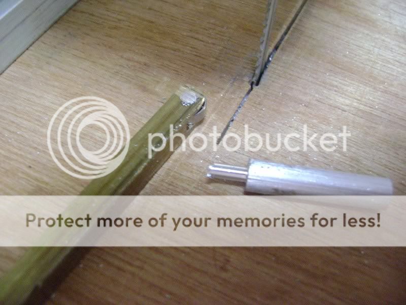
I'm going to reuse the piece that I screwed up previously.  It should still work...


The made in China hand press I bought from Hup Hong today. Slightly over SGD200 including tax.  Its a 50kg press with a 10mm hole for the pin.  I've nothing to insert in there yet.  Will be using the edge to press instead.


Turning another piece of aluminium to 3.05mm. This time, I kept the length shorter to reduce the chance of bending it during press fitting.


After drilling the 3mm hole 3mm away from the edge, I set it up on the tilting angle plate at 45 degree and milled off both side.

This is just to try out the new toy I bought a few weeks back.


The result.  Some filing will be done next.


After filing.  Ok, not the best looking radius but this was my best effort...


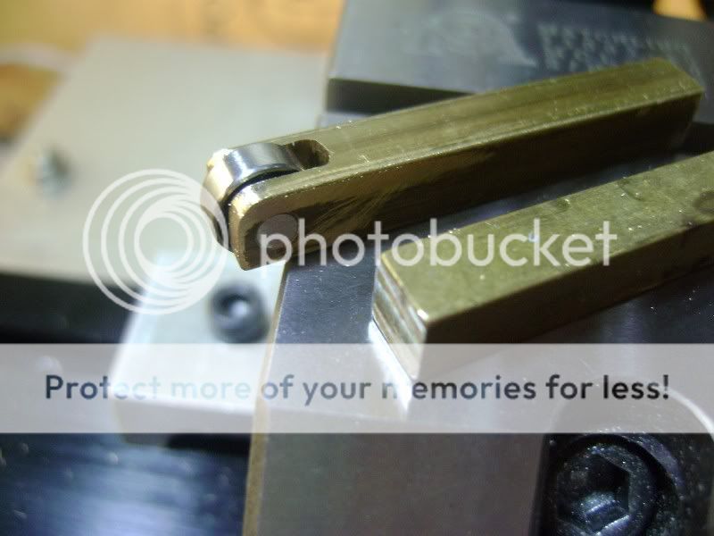
Ball bearings fitted.  Couldn't take a pic while press fitting as I was leaning my weight on the little press to push the aluminium pin in.

Ugly looking but they work!!!


All 3 installed on the steady rest. Actually, they're part of the steady rest... what am I talking about....


Testing done using a short piece of steel stock. Didn't bother to dig out the longer one to test.  All bearings rotates as they should.


Ok.  One project down for the machine.  Some time left before my dear wife reaches home.  I quickly setup the mill to try out 3D milling of a human face.  The attempt failed badly.  I'm reviewing the toolpath generated and the parameters I input.  Will do up a post on that next time.

Here is what it should look like:


Simulated using Bobcad included package - Virtual CNC for Mill.

I screwed up big time on this job.  Lots of chatter and the 6mm ballnose I was using cut into the face!!!


That's all for tonight.  Time to hit the bed.  Its 1.31am and I've a long day tomorrow.

Sunday, September 19, 2010

Ball Bearings Steady Rest - Failed attempt

I've been wanting to do this but kept pushing back for other projects.  Finally decided on Friday night that I'll get started on Saturday when I was trying to hold a long piece of round stock in the steady and had problem due to the uneven surface of the stock.

For my friends who are not into machining, there are 3 brass pieces in the steady to support longer work piece for machining on a lathe.

I started with a long piece of 1/4" square brass stock.  The 1st piece went well without any major mishap.  The slot was milled with the stock clamped horizontally.  This works ok as I'm able to get in with a single pass but very very slow feed.  The pin went in well too with the help of the Proxxon drill press as my arbor press.  Hope I didn't spoil the bearings in spindle or any other things.

The 2nd piece was screwed.  Everything went well till I was pressing in the pin.  The hole on the brass square is a little oversized (maybe by about 0.1mm to 0.2mm).  I couldn't seem to press the pin in all the way.  Ended up with the pin bended.

Got to stop work then to bring the family out for dinner.  No chance to continue after that.


Turning down aluminium rod to 3mm


Milling the slot for the ball bearing after the axle hole is drilled.


Ready for assembly


Pressing in the pin using my Proxxon drill press.  Bearing able to rotate freely


Sawing off the excess


1st piece done.  Not very good looking but it works.


For the 2nd piece, I decided to try rounding off the edge. This is from a video I watched online.  You can see from the side facing the camera that I turned the workpiece too much...


This time I milled the slot with the workpiece vertical. A square was used to ensure the part being perpendicular to the table.  This is to have the square bottom.


This one looks a little nicer than the 1st piece.


Press fit went wrong.  I don't know what's wrong.  Couldn't seem to get the pin in this time. The pin hole on the brass square is a little too big.  The pin was turned to 2.99mm in diameter.


I'll continue in my next session.  This was supposed to be a 1 to 2 hrs job (given my current level of skill, or the lack of).

Let's see if I can complete the 3 arms.

Thursday, September 16, 2010

Pawn Production

Get to spend some time in the shop tonight.  Started wanting to finish up the "probing stick" for the bro who is a diver with the carabiner hook I bought in between my meetings today.  Some problems which I can't solve at this point shifted my attention to the lathe.

Last Saturday afternoon, I spent some time wiring up the motors on the lathe to connect them to the Soigeneris Stepper Drive (http://www.soigeneris.com/STDR_4C-details.aspx).  Tonight, I was ready to test the now CNC lathe with the chess piece I planned to cut.  Some pics as usual with a couple of videos at the end.


The 25mm round stock being "sliced" off on the bandsaw to roughly square up the ends.  The Sherline vise was use to hold the stock and was guided by a straight edge clamp mounted onto the bandsaw table.


The gcode running...


Program completed.  Rather rough as I did not specify the finishing cut during the CAM stage.  Nothing can't be smoothen out with files and sandpapers.


After touching up with files, sandpapers, and brasso...  Nice...


I was to cut off the excess stock but changed my mind.  The new plan is to do some engraving on it and dress it up a little more to make it into a base.


Some videos taken during the cut.  Pardon me for the bad quality.  They were all taken using my iPhone with one hand while the other hand was on the e-Stop in case of screw-up.


The rubbing of the back of the tool against the stock wasn't as bad as I first thought.  It was more apparent only towards the end.


I was rather busy removing swarf during the run.  Lots of lots of swarf was produced.  I was so afraid that the long strands may get entangled in the chuck.

I'll be doing a bigger piece with finishing cut the next round.  Maybe a queen for my dear wife.  Of course, more shop time is needed for the many things I would like to make (or rather, attempt to make).


Sunday, September 12, 2010

A Job For A Bro... Part 2

I went down to Mike's shop at Fook Hai Buiding to pick up the CNC ready Rotary Table late morning today.  The stuff is heavy!  Rushed back home almost immediately to set it up for the job at hand.


The test went on fine with the RT responding to the xbox controller.

While I was calling Mike to find out how I should mount it to the titling angle plate, this heavy chuck, made heavier with the stepper motor installed dropped!  It landed on the handwheel, creating quite a deep hole in the parquet floor.  Good that the RT is not damaged or dented but.... my feet was bleeding.... thank God, its just a scratch.  I should use some common sense...


The RT mounted on the Angle Tilting Plate fastened to the table of the mill.  I mounted the 3-jaw chuck to the RT with the supplied adapter.  In my excitement, I missed out taking pics of the drilling of the 3 holes...


Actually, I drilled more than 3 holes...

I mistook the 2 holes for holding the die in place are 30 degrees from the center hole.  I was wrong.  The should be 45 degree from center.

The next thing I did was learned from Luiz Ally (Tryally); I tap the 10"-32 holes using a cordless hand drill.  It was so much faster than the other methods I tried.  Spindle speed was set low.  But I'll only dare to do this for through holes in aluminium.


The 3 10"-32 screws were up next.  The one for the center hole was turned to a point while the other 2 were rounded to match the dimples on the die.


Done and mounted to the tailstock.  I'm ready to cut the threads.


Strange... I couldn't seem to start the cut.  The diameter seem a little too big.  So the portion to be threaded was turned down a little more and now it threaded alright.

But... now it is too small for the snap bolt.  Got to saw it off and start over.


For the fun of it, I loctite the parts together.  The spring in the snap bolt has to be shortened to have the stainless steel rod seated properly and to allow the snap bolt to be pulled back.


To close off today's post, a short video of the RT while I was playin with it is presented:


Saturday, September 11, 2010

Making the 1" Tailstock Die Holder

This is a side tracked project made necessary while I was doing the job for a good friend of mine (see my post under "A Job For A Bro... Part 1").  The previous tailstock die holder I made was for an English made die.  The set of taps & dies I bought subsequently (M1 to M12) have smaller diameter of 1", which is too smaller for the holder.  So a new one is in order.

With the previous experience of making one, I started off rather well and quick till I had the problem of the stock being pulled out of the 3-jaw chuck while boring.  I started drilling from drill size of 4mm to the biggest my 3/8" jacob chuck can take (10mm).  The boring bar was next but I couldn't proceed as when the boring tool went into the hole, the stock came off.  It didn't happen the previous time.

Yesterday night, while I was in my dreamland, an idea suddenly hit me; why not drill & tap the 3/8"-24 hole for the morse taper adapter first and have the stock mounted on the spindle directly?  I'm sure those experience machinists or hobbyists would have done that from the start but hey, my proficiency is in the use of my Casio FC-200.  There are many advantages doing that, I reasoned.  For one, I wouldn't have the problem of the stock flying out of the chuck.  Two, I'll be assured of concentricity.  Three, my alignment will be perfect (or close to).

This morning, I woke up at 6.30am to get ready to work.  The idea works!  Not only the experience with the boring operation changed for the better considerably, I'm also able to turn to the entire length of the body of the holder - sweet!!!

Some pics are attached below.


The holder-to-be with the #1 MT adapter mounted in the spindle and the draw bar tightened (not shown).


The 25.4mm hole bored to 9.5mm deep.  The smaller internal hole was bored to 13mm to allow stocks to pass through the biggest tap in the set - 12mm.

The exterior of the body was turned down to approximately 34mm.


I was trying to "personalize" the holder, following Luiz Ally's demonstration on YouTube.  This Brazilian gentleman is really a master craftman. You should see his work.  Do a search for "Tryally" on YouTube.

But looking at what I did from the pic, you can see that I failed badly in that department...


Test fitted with the M5 die.  The holder is almost complete.  3 more holes to drill and tap; 2 to hold the die using the 2 dimples on it's edge and 1 for the split.  I should be using either 10-32 or M5 screws, turned to almost a point at their tips, as that are the 2 sizes I've the drill for.  I'm leaving the holes till tomorrow.  Arranged with Mike of sgTooling.com to pick up the rotary table so that I can drill the 3 holes right where they belong.


Frankly, despite the failed attempt to personalize the holder, I still feel rather proud of the result I get.  The dimensions of the part are very much closer to what I'd in mind, compared to the first one I did.  This one looks much better too.

Wednesday, September 8, 2010

A Job For A Bro... Part 1

A good friend of mine is into scuba diving and he tasked me to devise a way to fasten a stainless steel rod of 8mm diameter, around 400mm length, to a snap bolt.  The rod, according to him, will be used to tap the oxygen tank of diving buddies for signalling and to brush away sea urchins if they refused to move away.

The stainless steel rod was provided.  I was told that it was a spear in its glorious days.  Cutting off the threaded tip used for mounting the spear head and the other end for hooking on to the bow (I'm guessing here...) should leave me with enough length to make 3 pieces.

Not many pics were taken as I've yet to complete the job due to some problems...


Cutting the snap bolt.  This fella has tough skin but cut easy once the blade passed through the outer shell.


The rod was then cut using the Proxxon Mitre Saw.  I'm getting to love this machine.  Bought it from Mike of sgTooling.com a while back.


Turned down one end to 5mm for M5 threads.


The snap bolt was tapped M5.  Left some space for the spring to allow the bolt some room to move.  Don't know will the joint be too weak.  Planned for Loctite permanent thread lock.  I'm not into welding.


This was where the problem started. I was making a die holder to accept the set of metric die I bought. They measured 1" in diameter.  The last one I did was too big.

After drilling to 10mm, I started boring on the lathe.  The workpiece was pulled out of the 3-jaw chuck twice in a row.  First time encountering this.  Maybe I should reduce my depth of cut to less than 0.25mm per pass.

I ended the session tonight due to the effect of medication.  Time to wrap up and hit the bed.

Sunday, September 5, 2010

My attempt in making tool holders for A2Z QCTP - Failed Attempt

The session I had ended badly.  I was drilling the 4mm hole on the lathe for the tiny boring bar to find that the hole wasn't parallel to the body of the tool holder when the drill exited the opposite side.  I told myself it is alright as I still have the use of one side and that the QCTP can be adjusted to the angle I need before fastening it down to the cross feed table.

With that in mind, I proceeded with the drilling of the cross hole to accept a 10-32 screw to hold the boring bar.  As usual, I started with a centre drill before introducing the 4mm twist drill.  The only different this time was, the hole locations were centre punched.  The tip of the centre drill snapped off as soon as I bring down the spindle. I went on to do flip the 2 ended centre drill around and tried again - the other tip also snapped off.  But this time, I get to see what happened; I wasn't in total alignment with the punch marks with the tip of the centre drill.

To try saving my work, I relocate the holes and push through using the 4mm twist drill without any centre drilling or punch mark.  It went on well.

Though I've not completed the single trial piece of the tool holder, I've learned a few things:

1) Assuming my mill was properly trammed, to square the vise to the mill, I need to also indicate the bottom of the vise and not just the clamping face of the fixed jaw.
2) Don't centre punch when I am using the centre drill unless I'm sure that the spindle is lined up to the hole.
3) If I've no confident in drilling parallel to the work piece on the lathe with the workpiece fastened to the cross slide, use the mill or drill press after marking the hole location.
4) Reduce the width of the slot for dovetailing.  I'll have a firmer grip on the QCTP.

Thank God that I decided to cut out a small piece from the stock to test this out.  Though milling the slot and the dovetail took quite a while to complete, I don't end up with the whole batch going into waste.

Some pics:


The tiny boring bar not being aligned to the body of the tool holder.

Note the dimple above the cap screw. There is a tip of the centre drill inside.  Cap Screw for test only. I've not gotten the set screw yet.


The other end of the mounting hole is too close to the edge.  I drilled through so that I can use the 2 sides.  Should have just drill the 2 holes individually.


My new toy: Proxxon Parallels.  They're out by only 0.0005mm!  Fantastic for the price I paid - S$180++!!!

This set was bought from Mike of sgTooling.com.  My machines and accessories were from him too.  Nice chap to work with.


I'm going back to tramming my mill again in my next session in a week or 2.  Some company event next weekend.  The vise will be indicated in properly this time.  No more excuse not to get this right.